


2
REC Installation Manual - REC Solar Panels - IEC
61215
/
61730
Rev L
-
09
.
21
Ref: PM
-
IM
-20
CONTENTS
LIST OF FIGURES
Fig.
1
: Clamp specifications
7
Fig.
2
: Panel quarter divisions
7
Fig.
3
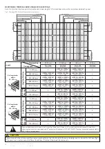
: Clamping of REC TwinPeak
4
Series panels with rails parallel to
short side of the panel
8
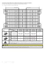
Fig.
4
: Clamping of REC TwinPeak
4
Series panels with rails parallel to
long side of the panel
9
Fig.
5
: Clamping of REC TwinPeak
4
Series panels using short rails
10
Fig.
6
: Clamping of N-Peak panels parallel to short side of module
11
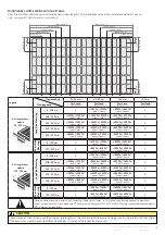
Fig.
7
: Clamping of N-Peak panels parallel to long side of module
12
Fig.
8
: Clamping of REC N-Peak Series panels using short rails
13
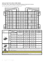
Fig.
9
: Clamping of REC N-Peak
2
Series panels with rails parallel to
short side of the panel
14
Fig.
10
: Clamping of REC N-Peak
2
Series panels with rails parallel to
long side of the panel
15
Fig.
11
: Clamping of REC N-Peak
2
Series panels using short rails
16
Fig.
12
: Mounting holes: REC
60
-cell panels
17
Fig.
13
: Mounting holes: REC
72
-cell panels
17
Fig.
14
: Device specifications for mounting holes
17
Fig.
15
: Mounting hole installation example
17
Fig.
16
: Drainage and grounding holes
18
Fig.
17
: Connector mating matrix
19
Fig.
18
: Minimum cable bend radius
19
Fig.
19
: WEEE symbol
20
Fig.
20
: Panel dimensions: REC TwinPeak
4
Series
21
Fig.
21
: Panel dimensions: REC TwinPeak
4
Black Series
22
Fig.
22
: Panel dimensions: REC N-Peak Series
23
Fig.
23
: Panel dimensions: REC N-Peak Black Series
24
Fig.
24
: Panel dimensions: REC N-Peak
2
Series
25
Fig.
25
: Panel dimensions: REC N-Peak
2
Black Series
26
Fig.
26
: REC
60
-cell panels MLPE device installation zones
28
Fig.
27
: REC
72
-cell panels MLPE device installation zones
28
INTRODUCTION
3
SAFETY MEASURES
4
PANEL HANDLING
5
CHOOSING AN INSTALLATION LOCATION
5
ELECTRICAL INSTALLATION
6
MECHANICAL INSTALLATION
6
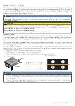
PANEL INSTALLATION
7
Securing of Panels
7
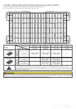
Installation of REC TwinPeak
4
Series panels
8
Mounting REC TwinPeak
4
Series panels with continous rails parallel to short side of the panel
8
Mounting REC TwinPeak
4
Series panels with continous rails parallel to long side of the panel
9
Mounting REC TwinPeak
4
Series panels with short rails
10
Installation of REC N-Peak panels
11
Mounting REC N-Peak panels with continuous rails parallel to short side of the panel
11
Mounting REC N-Peak panels with continuous rails parallel to long side of the panel
12
Mounting REC N-Peak panels with short rails
13
Installation of REC N-Peak
2
Series panels
14
Mounting REC N-Peak
2
Series panels with continous rails parallel to short side of the panel
14
Mounting REC N-Peak
2
Series panels with continous rails parallel to long side of the panel
15
Mounting REC N-Peak
2
Series panels with short rails
16
Mounting methods: Slide in systems
17
Mounting methods: Mounting holes
17
Drainage holes
18
CONNECTIONS AND CONNECTORS
19
CABLE MANAGEMENT
19
PANEL MAINTENANCE
20
RECYCLING
20
DISPOSAL OF OLD ELECTRICAL AND ELECTRONIC EQUIPMENT
20
PANEL CHARACTERISTICS
21
Technical Properties: REC Twinpeak
4
Series
21
Technical Properties: REC TwinPeak
4
Black Series
22
Technical Properties: REC N-Peak Series
23
Technical Properties: REC N-Peak Black Series
24
Technical Properties: REC N-Peak
2
Series
25
Technical Properties: REC N-Peak
2
Black Series
26
ANNEX
1
: INSTALLATIONS ON WATER PLATFORMS
27
ANNEX
2
: INSTALLATIONS USING MODULE LEVEL POWER ELECTRONICS
28
EC DECLARATION OF CONFORMITY
29
DOCUMENT HISTORY
30