生活美好,臂不可少
http://www.realman-robotics.com
43
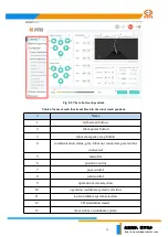
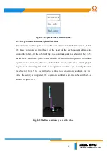
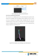
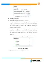
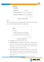
Fig. 8-24 Step mode demo.
8.2.18 Robot Position and Posture Information Display
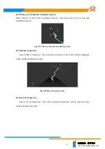
The position (X, Y, Z) denotes the center of tool flange (the selected tool coordinate
system) in the selected coordinate system (from one of Base coordinate system, end
coordinate system, and customized coordinate system). The pose (RX, RY, RZ)
expresses the rotation arc relative to the selected coordinate system, resulted from
rotating along the selected coordinate system in a certain order.
Fig. 8-25 A robot end position and posture display demo.
8.2.19 Speed Display
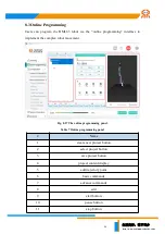
Drag the slider to set the percentage of the robot speed with respect to the designed
maximum speed.
Fig. 8-26 The speed setting slider.
8.2.20 Origin Pose Button
Origin pose: Long-hold
can reset the robot to the origin. Release the
button to stop the movement.
8.2.21 Initial Pose Button
Initial pose: Long-hold
can reset the robot to its initial. Users can
also freely set the initial position and pose of the robot according to the descriptions in
the section of the initial pose calibration (Section 8.4.2.4) through the teach pendant
software. Release the button to stop the movement.


