background image

UM-1096 

Revision A 


Chapter 2 


General Description 


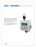
The 

Sense

Point

 gas detector is a 120-240VAC, or 

10-30VDC, powered gas detector for toxic, 

oxygen, combustible, VOC and CO2 detection, 

with a color backlit LCD display, 4-20mA output, 

Modbus communications and relays.


All models use RC Systems latest Generation II 

Smart Sensor technology, providing smarter gas 

detection with simplified solutions.


Summary of Contents for 10-0517

Page 1: ...8621 Hwy 6 Hitchcock TX 77563 409 986 9800 www rcsystemsco com UM 1096 Revision A SensePoint Operations Manual...

Page 2: ...3 2 Mounting the Enclosure 4 3 3 Power and Analog Outputs Wiring 6 3 3 1 110 230VAC 15W Power Wiring 6 3 3 2 4 20mA Output Wiring 6 3 4 Option Board Wiring 7 3 4 1 SensePoint RS 485 Option Board 7 3 4...

Page 3: ...re 19 6 1 Regular Maintenance 19 6 2 Sensor Replacement 19 Appendix 1 Gas Detector Specifications 20 Appendix 2 Sensor Specifications 22 Appendix 3 Modbus Table and Operations 24 System Registers 25 R...

Page 4: ...UM 1096 Revision A III Drawings 44...

Page 5: ...ay Option Wiring 8 Figure 6 Remote Sensor Option 9 Figure 7 Stainless Steel Sensor Head 10 Figure 8 SensePoint Data Display Screens 12 Figure 9 SensePoint Fault Screen 12 Figure 10 SensePoint and SenS...

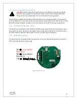
Page 6: ...NT UNLESS POWER HAS BEEN SWITCHED OFF OR THE AREA IS KNOWN TO BE NON HAZARDOUS Use a properly rated CERTIFIED AC power mains cable installed as per local or national codes A certified AC power mains d...

Page 7: ...or 10 30VDC powered gas detector for toxic oxygen combustible VOC and CO2 detection with a color backlit LCD display 4 20mA output Modbus communications and relays All models use RC Systems latest Ge...

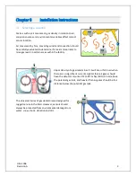
Page 8: ...aise gas levels in certain areas within the facility Vapor density of a gas determines if it will rise or fall in air when there are no significant currents Lighter than air gases should have the dete...

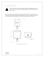
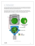
Page 9: ...e Figure 2 for mounting dimensions of the sensor housing After you have determined the appropriate location for your gas detector it is important to securely mount the gas detector using the predrille...

Page 10: ...UM 1096 Revision A 5 Figure 2 Remote Sensor Enclosure Mounting Dimensions...

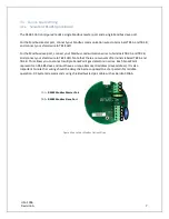
Page 11: ...on boards mount to the back of the display assembly and power input and output wires mount to the power supply board 3 3 1 110 230VAC 15W Power Wiring The SensePoint is powered by a 110 230VAC 15Watt...

Page 12: ...TB2 B and connect your shield wire to TB2 SHLD Note that there are two sets of terminals labeled TB2 A and TB2 B This allows you to connect multiple SensePoint gas detectors in series Each SensePoint...

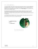
Page 13: ...oth The relay terminals are labeled NO Normally Open NC Normally Closed or C Common or pole These designators correspond to the shelf or de energized state of the relays When a relay is in Failsafe mo...

Page 14: ...oard communicates to the SensePoint by utilizing one of the RS 485 communication ports located on the option board Connect 24VDC and ground wires to the 24V and GND terminals on TB1 or TB2 of the Remo...

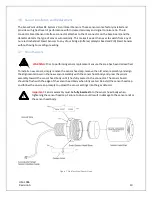
Page 15: ...t Sensors WARNING Prior to performing sensor replacement ensure the area has been declassified To install a new sensor simply remove the sensor head cap remove the old sensor assembly and align the al...

Page 16: ...g steps 1 Apply power to the gas detector 2 Verify the detector has begun startup Note Once the detector is on the data screen you may notice high or low values out of the full scale range These value...

Page 17: ...ate has been reached It is recommended to set the fault alarm level to 10 of the span value For example if an H2S sensor is installed with a span value of 100 the fault should be set at 10 or if an ox...

Page 18: ...lways set to yellow and the Fault alarm is always set to Red Figure 10 SensePoint and SenSmart Alarm Screens When an alarm level is reached the display will change to the user defined color and the al...

Page 19: ...more often if sensor is known to have been exposed to gas for extended periods of time Periodic bump tests are recommended if detector has potentially been exposed to incompatible gases to ensure cor...

Page 20: ...ALUE setting RC Systems typically recommends choosing a value at 50 of full scale 2 A cylinder of Zero Air unless you are confident there is no target gas potentially present in the area 3 A flow regu...

Page 21: ...UM 1096 Revision A 16 5 Sufficient length of flexible tubing to connect the regulator to the calibration adaptor...

Page 22: ...it key to enter Cal Mode 3 Apply a clean Zero Gas using the Calibration Cup or be sure there is no background target gas in the monitored area After the reading is stable swipe the Edit key to set the...

Page 23: ...and no calibration settings are changed during the test To perform a bump test briefly expose the sensor to a gas of known concentration above the Low Alarm set point and check to ensure the display...

Page 24: ...may be detected by an operational detector depending on the sensor type So proper precautions should be taken RC Systems recommends calibrations Immediately prior to placing a gas detector in service...

Page 25: ...tance 600 ohms 24VDC Three programmable relays MODBUS RS 485 serial interfaces Environmental Operating range 40 C to 60 C Sensors include sensor heater for low temperature operation Relative humidity...

Page 26: ......

Page 27: ...m 100ppm Flourine F2 1 31 0 1ppm 25ppm 1ppm Hexane C6H14 2 97 500ppm 1100ppm 0 100 LEL Hydrazine N2H4 1 1 C 0 03ppm Ca 50ppm Ca 1ppm Hydrogen H2 0 07 asphyxiant 250ppm 5000ppm Hydrogen H2 0 07 asphyxi...

Page 28: ...to 131 0 to 99 20 40 60 EC 200 22 to 122 15 to 90 20 40 60 EC 30 80 14 to 104 15 to 90 20 40 60 IR 5 10 40 to 158 up to 99 Millenium sensor 20 40 60 EC 30 120 14 to 104 20 to 95 20 40 60 EC 80 22 to 1...

Page 29: ...de 3 write coil as well as function code 6 and 16 write holding registers These function codes can be used to write configuration parameters to the SensePoints Writing parameters that span multiple re...

Page 30: ...nel State Mismatch Channel State No Sensor Channel State Sensor Error Channel State Comm Error Channel state Scaling Error Analog Output 31001 Unsigned Integer 4 N A 1 12 bit value 800 4mA 4000 20mA S...

Page 31: ...nt Data Time 40023 Time 3 6 16 2 Current Time Warmup Time 40027 Integer 3 6 16 1 Warm up delay minutes Cal Purge Time 40028 Integer 3 6 16 1 Cal purge delay minutes Block Negative 40029 Selection 3 6...

Page 32: ...gered Standard Relay 3 State 32022 Selection 4 N A 1 0 Clear 1 Triggered Warmup 32025 Selection 4 N A 1 0 No 1 Yes Standard Relay 1 Flashing 32026 Selection 4 N A 1 0 No 1 Yes Standard Relay 2 Flashin...

Page 33: ...s Relay 2 Failsafe 40118 Selection 3 6 16 1 0 No 1 Yes Relay 2 Refresh Time 40119 Integer 3 6 16 1 Relay 3 Source 40126 Selection 3 6 16 1 0 Alarm 1 1 Alarm 2 3 Alarm 3 3 Fault 4 Cal Mode 5 Cal Zero 6...

Page 34: ...4 Floating Pt Span Setpoint 42003 32 Bit Floating Point 3 6 16 2 Modbus 32 bit IEEE 754 Floating Pt Zero Value 42005 32 Bit Floating Point 3 6 16 2 Modbus 32 bit IEEE 754 Floating Pt Span Value 42007...

Page 35: ...Config Error 33025 Selection 4 N A 1 True if config error I O Error 33026 Selection 4 N A 1 True if input output error Calibration Flag 33027 Selection 4 N A 1 True if calibration in progress Error Fl...

Page 36: ...m 3 Color 43026 Selection 3 6 16 1 0 Red 1 Orange 2 Blue Alarm 3 Enabled 43027 Selection 3 6 16 1 0 No 1 Yes Data From 43031 Selection 3 6 16 1 0 Sensor 1 Remote Sensor 2 4 20mA Min Raw 43032 Unsigned...

Page 37: ...Temperature Comp 3 16 4 32 bit FP Gain 32 bit FP Offset Temp Comp 20C 43123 Temperature Comp 3 16 4 32 bit FP Gain 32 bit FP Offset Temp Comp 30C 43127 Temperature Comp 3 16 4 32 bit FP Gain 32 bit F...

Page 38: ...u provides access to user configurable input parameters This includes Alarm settings for all three alarms access to the data from menus where you can adjust sensor settings for various types of sensor...

Page 39: ...ill set the relay to its normal state even if the alarm condition still exists This can be useful for silencing audible devices driven from the relay o Refresh When enabled this feature refreshes the...

Page 40: ...tion is gone This is useful for continuing an alarm function such as operation of an exhaust fan for a period of time after the alarm condition clears Deadband Alarm 1 2 3 Deadband allows forcing low...

Page 41: ...t Voltage set s the voltage being supplied to bridge type sensors o Set Balance adjusts the balance of a catalytic bead sensor and must only be adjusted with ZERO gas on the sensor o Set PGA is the ad...

Page 42: ...r for communicating with the selection of 10mW 100mW 200mW 1W o Hand Shaking o Wakeup is the amount of time set between normal transmitting o TX Retries is the amount of times the transmitter will try...

Page 43: ...ntered o Byte Order determines WORD and BYTE alignment of data at the remote Modbus transmitter when sending this 4 byte IEEE floating point values o LED Enable enables the RX and TX LEDs to flash gre...

Page 44: ...nd display value Diagnostics The Diagnostics Menu is entered by swiping the edit key entering the technician s sequence 4 swipes of the UP key and then swiping the edit key again o Analog Output The A...

Page 45: ...t Shield Board 10 0532 SenSmart Relay and RS 485 Modbus Option Board 7 Accessories 10 0198 Sensor Head Splash Guard with Remote Cal Port 10 0203 Sensor Head Calibration Adaptor 10 0270 Stainless Steel...

Page 46: ...the correct alias Appendix 4 Verify Modbus wires are connected to the correct terminals Chapter 3 4 My SensePoint is responding to gas but the controller is in fault Verify the analog signal wire is c...

Page 47: ...UM 1096 Revision A 42 Be sure to follow the calibration procedure For Technical Support call 409 986 9800 x160 or email support rcsystemsco com...

Page 48: ...id reply from Modbus or wireless device 10 I O Error Red Indicates a failure to communicate between I O board electronics 11 Config Error Red Indicates interface for Modbus wireless is configured for...

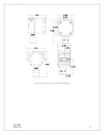
Page 49: ...UM 1096 Revision A 44 Appendix 9 Drawings Drawings Figure 13 Mounting Dimensions...

Page 50: ...UM 1096 Revision A 45 Figure 14 10 0517 CPU Board Figure 15 10 0533 I O Board...

Page 51: ...UM 1096 Revision A 46 Figure 16 10 0532 Modbus Relay Board...

Reviews: