background image

V1.1

Shanghai Empower Technologies Co., Ltd. © Copy Right

www.empower.cn

BM114 SERIES 6KW Laser Cutting Head User Manual

10 | 11

3 System Installation Commissioning

3.1 EtherCAT Installation

3.1.1

Distribution

AheadTechs  30W DC motor:
The motor is DC servo motor, which should connect the end of the drive L1, L2 respectively with+24V
and 0V, and the driver power supply L1C and L2C should connect to 220V exchange L and N.(24V power
supply is customer-owned)

When EtherCAT is in bus model, the driver in TSM must be placed before 150P device, C5 interface is
CAN IN, C6 interface is CAN OUT

Limit signal:

Black

White

Brown

Blue

Lower limit

Upper limit

+24V

0V

Note: the limit sensor is active low, and the signal is often closed, and it continuously outputs 0V

signal when it is not triggered. When the configuration bus scheme is used, it needs to connect the relay and be
switched to active-high output.

The limit diagram is shown in Figure 4-1.

3.1.2

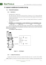
Configure the Hardware

Hardware: bus model driver must be connected before DX-150P. As per: Host - F axis drive - 150P - EIO500 -

EDS88C0 (Figure 4.2), connect the F-axis limit and power cord to the I/O, remember the corresponding pin end

Summary of Contents for BM114 Series

Page 1: ...BM114 SERIES 6KW Auto Focusing Laser Cutting Heads User Manual Hotline 400 670 1510 Fax 021 6760 1511 Email sales empower cn Add No 72 Lane 1500 Xinfei Road Songjiang District Shanghai ...

Page 2: ...nual makes a detail introduction about the use of BM114 laser cutting head including installation setup operation and service etc Please directly contact us if you have other things to know Please read these instructions carefully before use the series cutting head and relative equips This will help you to use it better Because the product keeps renewing please note the product you receive may dif...

Page 3: ...EtherCAT Installation 10 3 1 1 Distribution 10 3 1 2 Configure the Hardware 10 3 1 3 eInterface Settings and Adjustments 11 3 1 4 Cutting Parameter Setting 13 3 2 BC with position mode 14 3 2 1 Distribution 14 3 2 2 Software Settings 14 3 2 3 Interface Operation 15 3 3 BC with velocity mode 16 3 3 1 Distribution 16 3 3 2 Software settings 16 3 3 3 Interface Operation 17 4 Beam Adjustments and Focu...

Page 4: ...eplace Nozzle 24 5 4 Troubleshooting of Driver 24 5 4 1 Fault Analysis of AheadTechs Driver 24 6 BM114 System Constitution 26 6 1 System Constitution Bus 26 6 2 System Constitution Non bus position loop BC 27 6 3 System Constitution Non bus position loop BC 28 7 Mechanical and Optical Configurations Diagram 30 7 1 Cutting Head Shape 30 7 1 1 Focus length 32 ...

Page 5: ...ates and the automatic cutting of plates of varies thickness and material The product can be equipped with D37 composite lens group to integrate the beam a variety of interface settings so that it can be used with a variety of fiber lasers optimized optical and water cooled design allows the laser head work under high power steadily for a long time 1 1 Product Advantages Optimized optical configur...

Page 6: ... module The collimation function of the optical fiber is collimated after the incident laser is collimated into a parallel beam and the function of tuning Focusing driving module The collimated beam is focused into a concentrator beam with high power density and the focus position is automatically adjusted by the driving device Protective lens module the protective lens protects the focusing lens ...

Page 7: ...ter cooled interface BM114 laser processing head has 3 sets of water cooled channels which direction of water entry and exit can be arranged arbitrarily It is important to note that when the laser power is greater than 500 watt hours it is recommended to use water cooled as you can see from Figure 3 2 the position and amount of the water interface and the right table details the recommended flow v...

Page 8: ...arance of dust and hydrocarbon Stainless steel fittings are recommended at the same time must use filters which can remove a minimum of 0 01 micron particle to purify A pressure gauge with a stainless steel diaphragm is recommended Industrial pressure gauges suck in air Rubber diaphragm produce hydrocarbon by aging or other factors CAUTION Gas interface can not be replaced arbitrarily especially d...

Page 9: ... output and the two are normally closed output mode high level and low level signal are output by the sensor when not triggered electric relay should be self installed when necessary to carry on the high low level or the normally open and normally closed conversion CAUTION All wiring is in the state of power failure and the power can be debugged after inspection 2 4 Fiber Input Interface BM114 is ...

Page 10: ...H red mark and insert straight to bottom Then turn the QBH handwheel clockwise It is in place when you hear the Da sound then pull the handwheel up and turn clockwise again see Figure 3 4 If when the fiber connector insert into the interface the red dot on fiber is too far away from the red dot on laser head interface causing an out of alignment insertion when can refer to steps below to adjust th...

Page 11: ...odel the driver in TSM must be placed before 150P device C5 interface is CAN IN C6 interface is CAN OUT Limit signal Black White Brown Blue Lower limit Upper limit 24V 0V Note the limit sensor is active low and the signal is often closed and it continuously outputs 0V signal when it is not triggered When the configuration bus scheme is used it needs to connect the relay and be switched to active h...

Page 12: ...onfig mode and then scan the devic In the pop up dialog box select the new add drive and the 150P on the right Select before add the drive select the F axis in the NC axis and drive the link to the F axis In the corresponding card and the corresponding pin link to PLC in the F axis positive and negative limit field lower limit biFNegLimit upper limit biFPosLimit Activate TSM run HMI 3 1 3 eInterfa...

Page 13: ...meter default parameter shown in Figure 4 4 AheadTechs drive bus pulse 10000 pulse loop Zoom speed is recommended to set the value to 50 100mm s 5 F axis zero return zero focus coke zero focus position and zero position coincides with the same point steps 1 The parameter point position is set to 0 2 F axis zero return with barrel moving downward and touches lower limit scale at bout 13 note Upper ...

Page 14: ...e upper and lower limits into the positive focus and negative focus of the F axis 7 Setting the corresponding soft limit parameter Note negative return to zero must be true reverse wait sync pulse acceleration acceleration factor speed of change need not be modified according to the default mode 3 1 4 Cutting Parameter Setting When cutting different plates in the process parameters fill in differe...

Page 15: ...d the driver power supply L1C and L2C should connect to 220V exchange L and N 24V power supply is customer owned Limit signal Black White Brown Blue Lower limit Upper limit 24V 0V Note the limit sensor is active low and the signal is often closed and it continuously outputs 0V signal when it is not triggered The limit diagram is shown in Figure 4 1 3 2 2 Software Settings Open the platform configu...

Page 16: ...peration 1 Inch J axi check up if the action is normal distance to pitch and direction 0 scale moves up to J 2 Slow moving the J axis so that it meets the positive and negative limit check whether the direction the signal is normal or not 3 Click zero returning icon J axis move to negative direction and return zero again when touches negative limit at the same time the position of zero point coinc...

Page 17: ... motor is DC servo motor which should connect the end of the drive L1 L2 respectively with 24V and 0V and the driver power supply L1C and L2C should connect to 220V exchange L and N 24V power supply is customer owned 2 Limit Signal Black White Brown Blue Lower limit Upper limit 24V 0V Note the limit sensor is active low and the signal is often closed and it continuously outputs 0V signal when it i...

Page 18: ...e moving upward is J 2 Slow moving J axis so that it touches the positive and negative limit detect whether the signal and direction is right The positive and negative limit wiring has the pipe sleeve mark 3 Click zero returning icon J axis move to negative direction and turn to zero again after touching the negative limit At the moment zero point position coincides with zero focus position the ze...

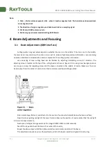
Page 19: ... Lens centering of laser cutting head can be finished by adjusting Collimating mirror X Y direction The adjusting screw is located on the top of the cutting head as shown in Figure 5 1 By using inner hexagon spanner can loosen or screw the adjusting screw until the beam is located in the middle of nozzle Make sure the laser beam output from the center of nozzle A method commonly used tape dotting ...

Page 20: ... and find out the scale corresponding to the smallest hole is zero coke that is the focus is just at the end of the nozzle section 5 Maintenance 5 1 Cleaning Lens It s necessary to maintain lenses regularly because of the characteristic of laser cutting process Once a weak cleaning the protective lenses is recommended The collimating lenses and focusing lenses are recommended to clean once every 2...

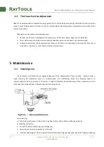
Page 21: ...f Collimating Protective Lenses The protective lens are a fragile part and need to be replaced after damage As shown in Figure 6 1 open the buckle open the cover of protective lens pinch the two sides of the drawer type lens holder and pull out the base of protective lens Remove the pressure washer of the protective lens remove the lens after wearing fingertips Clean the lens lens holder and seal ...

Page 22: ... clean into the drawer type lens holder Re install the seal ring Re insert the collimating protective lens holder to the laser processing head cover the lid of collimating protective lens and tighten the locking screw Note It is not allowed to directly pull out of the edge of the elastic seal ring which will damage the elastic seal ring very easily 5 2 3 Removal and Installation of Collimating Len...

Page 23: ...ropriately with force and re screw it into the collimating components Lock the screws of the collimating components Check whether the focus position is in the center of the nozzle hole before use if it is not in the center it is necessary to carry out center regulating operation again 5 2 4 Removal and Installation of Focus Lenses Removal and installation of focus lenses refer to the following ste...

Page 24: ...ence shown in figure 6 7 reassemble and lock the screw Check if the focus position is at the center of nozzle If not you need to refer to the 3 1 step to reset the operation 5 3 Replace Nozzle Connector In the laser cutting process the laser head will inevitably be hit so it is necessary to replace the nozzle connectors 5 3 1 Replace Ceramic Body Unscrew the nozzle Press the ceramic body with hand...

Page 25: ...sures to be taken Insert and extract the network cable between the driver and the host computer again J1 Definition Position error is out of range Failure description Motor locked rotor or the motor is out of range Measures to be taken Power on the driver again and move in the opposite direction or increase the tolerance range of the position error r6 Definition Hall signal is illegal Failure desc...

Page 26: ...ered r25 Definition Pulse direction input line signal is interrupted Failure description A pulse direction signal is not connected Measures to be taken Check whether all pulse direction signals are connected correctly with the driver check whether the control lines are connected correctly u Definition Undervoltage Failure description The bus voltage is lower than the minimum value Measures to be t...

Page 27: ...V1 1 Shanghai Empower Technologies Co Ltd Copy Right www empower cn BM114 SERIES 6KW Laser Cutting Head User Manual 26 11 6 BM114 System Constitution 6 1 System Constitution Bus ...

Page 28: ...V1 1 Shanghai Empower Technologies Co Ltd Copy Right www empower cn BM114 SERIES 6KW Laser Cutting Head User Manual 27 11 6 2 System Constitution Non bus position loop BC ...

Page 29: ...V1 1 Shanghai Empower Technologies Co Ltd Copy Right www empower cn BM114 SERIES 6KW Laser Cutting Head User Manual 28 11 6 3 System Constitution Non bus position loop BC ...

Page 30: ...V1 1 Shanghai Empower Technologies Co Ltd Copy Right www empower cn BM114 SERIES 6KW Laser Cutting Head User Manual 29 11 ...

Page 31: ...V1 1 Shanghai Empower Technologies Co Ltd Copy Right www empower cn BM114 SERIES 6KW Laser Cutting Head User Manual 30 11 7 Mechanical and Optical Configurations Diagram 7 1 Cutting Head Shape ...

Page 32: ...V1 1 Shanghai Empower Technologies Co Ltd Copy Right www empower cn BM114 SERIES 6KW Laser Cutting Head User Manual 31 11 ...

Page 33: ...nghai Empower Technologies Co Ltd Copy Right www empower cn BM114 SERIES 6KW Laser Cutting Head User Manual 32 11 Opening type QBH 100mm 7 1 1 Focus length Focus distance 150mm FL 200mm FL 18 5mm cushion block ...

Reviews: