background image

Chapter 5: Standard Chart Operations

5-3

Re

m

o

vi

n

g a

 Ch

ar

Ca

rd

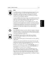
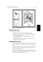
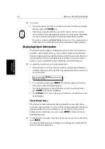
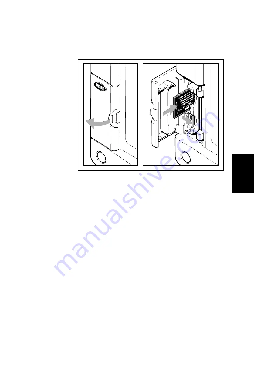
Figure 5-1:

Removing the Chart Card

Removing a Chart Card

To remove a chart card:

1. Open the card cover, at the lower left of the display front panel.

2. Press on the card you wish to remove, and move the top of the card to the

left to clear the retaining pegs.
The card will spring half-way out, enabling you to grip the card and
remove it from the slot.

3. Remember to close the card cover so that it clicks shut, to prevent water

from entering the card reader assembly.

Displaying the Chart Data

The new chart information will be displayed when you move the cursor into an
area covered by the new chart or, if it is already in the area, change the range
scale.

If an HSB Series repeater display is connected, the chart can also be accessed
by the repeater display. To see the chart you may need to zoom or pan, to
redraw the chart area to the screen.

The boundary of each chart digitized in the current card is defined by a box or
rectangle. (You can switch off the chart boundaries display if you wish, as part
of the chartplotter set up described in Section 7.5.)

D4158-1

Summary of Contents for HSB L760

Page 1: ...HSB Series L755 and L760 Fishfinder Owner s Handbook Document number 81169_3 Date November 1st 2000...

Page 2: ......

Page 3: ...GATION AID The chartplotter unit is only an aid to navigation Its accuracy can be affected by many factors including equipment failure or defects environmental conditions and improper handling or use...

Page 4: ...ndbook may occur from time to time for which liability cannot be accepted by Raytheon Raytheon is a registered trademark of Raytheon Company SeaTalk is a registered trademark of Raytheon Marine Europe...

Page 5: ...al dealer will be available to answer any questions you may have TFT LCD Displays The colors of the display may seem to vary when viewed against a colored background or in colored light This is a perf...

Page 6: ...are designed to the best industry standards for use in the recreational marine environment The designandmanufactureofRaytheonequipmentandaccessoriesconform to the appropriate Electromagnetic Compatib...

Page 7: ...Functions 1 12 1 4 Operating Controls 1 13 Trackpad and Cursor 1 14 Dedicated Keys 1 15 Soft Keys 1 16 Pop Up Menus 1 16 Database Lists 1 17 Chapter 2 Installation 2 1 2 1 Introduction 2 1 Selecting...

Page 8: ...ce 2 35 2 9 Integrated Systems 2 35 HSB High Speed Bus 2 36 SeaTalk and NMEA In 2 37 Using the SeaTalk Auxiliary Junction Box 2 42 Data Output 2 43 Data Conversion 2 44 2 10 Integrated System Checks 2...

Page 9: ...to a Waypoint 3 32 Make and Follow a Route 3 34 Review Your Passage Plan 3 36 Chapter 4 Fishfinder Operations 4 1 4 1 Introduction 4 1 4 2 Interpreting and Adjusting the Fishfinder Image 4 1 Fish Indi...

Page 10: ...a Route From the Database 5 18 Displaying Route Information 5 19 Using the Route List to Erase and Name a Route 5 21 Editing a Route 5 21 5 5 Following Routes and Going to Points 5 24 Follow a Route...

Page 11: ...de 7 6 Cursor Reference 7 6 Cursor Readout 7 6 Day Night L755 Monochrome Display 7 6 Help 7 6 Soft Keys 7 7 Key Beep 7 7 MOB Data 7 7 Menu Timeout Period 7 7 Units 7 7 Variation Source 7 7 Bridge NMEA...

Page 12: ...8 1 EMC Servicing and Safety Guidelines 8 2 8 2 Resetting the System 8 3 8 3 Problem Solving 8 4 How to Contact Raytheon US 8 5 How to Contact Raytheon Europe 8 6 Worldwide Support 8 7 Appendix A Spe...

Page 13: ...s on your system configuration and set up op tions so it may differ from the illustration How to Use This Handbook If you are installing the display system yourself you should read Chapter 2 before yo...

Page 14: ...ecific data such as fishfinder chart or radar data Repeater A unit capable of displaying data such as radar from the HSB Fishfinder Display Unit providingFishfinder Master and Radar Repeater functiona...

Page 15: ...ay via the HSB connection and can be displayed and controlled on any other HSB Series LCD or CRT display the repeater display In particular you can connect your HSB Series Fishfinder to a remote HSB S...

Page 16: ...data Provides full control of data from other HSB instruments Three full screen operating modes Fishfinder Chart Data Log if appro priate data is available View fishfinder and chart simultaneously Hal...

Page 17: ...ing to the target waypoint Nav Data Chart mode This shows sixteen data boxes providing navi gational data in the units specified in your set up Note that up to 6 of these data boxes are also available...

Page 18: ...hown The fishfinder screen includes a status bar that displays transducer frequency and indicates which auto settings are enabled Gain Color Gain Range Zoom and Frequency and alarm status fish and sha...

Page 19: ...the current depth Bottom Lock changes the operating mode to re set the bottom It pro vides a bottom up view the bottom is used as the reference its image is flattened and depths are displayed here Bot...

Page 20: ...plit horizontally Zoom Bottom Lock or A scope can be displayed with the dual frequency graph All of these options are available when the fishfinder is displayed in a half screen window Fishfinder Func...

Page 21: ...BTM LOCK A SCOPE AUTO G Z 0 100 7 9 52 3 200kHz 50kHz 200kHz 50kHz SPLIT 0 100 ft ZOOM FREQUENCY BTM LOCK A SCOPE AUTO G Z 200kHz 5 10 15 20 ft 80 0 ZOOM FREQUENCY BTM LOCK A SCOPE AUTO G SPLIT D5022...

Page 22: ...nless you turned them off in Chart Set Up as described in Chapter 7 and the current route is shown Information can be viewed on screen by positioning the cursor over a waypoint current route or chart...

Page 23: ...using the CUSTOM soft key The factory default settings for the Custom chart options are as follows ON Chart text chart boundaries depth contours navigation marks and land features OFF Caution and rou...

Page 24: ...ion including Ports and Tides if available View chart information if available for the Nearest Port Place Move Erase and Edit a Waypoint Goto Waypoint or Cursor Create Save Name Edit and Follow a Rout...

Page 25: ...atabase lists displayed on screen which enable you to edit items Note The cursoristhe cross hairsymbol visible onthe display Youmove the cursor using the trackpad and use it to select a position or it...

Page 26: ...any operations you cannot move the cursor around the screen if you cannot move the cursor using the trackpad check the default soft keysare displayed unlessthey have beenswitchedOFF insystem setup If...

Page 27: ...n release it This method is used for most key operations Pressand hold Pressthekeyandholditdownfor the lengthoftimestated for example 3 seconds and then release it When you press a dedicated key one o...

Page 28: ...f the following happens i The associated operation is performed e g 50 kHz ii A sub set of soft keys is displayed providing further functions iii A pop up menu is displayed providing further options A...

Page 29: ...items for editing Figure 1 7 Typical Database List As with pop up menus when a database list is on screen a set of associated soft keys is also displayed you use the trackpad to select an item from t...

Page 30: ...1 18 HSB Series L755 and L760 Fishfinder Database Lists...

Page 31: ...supply connecting the red wire via a 6 3A quick blow fuse to positive and the black wire to negative and using the simulator mode as described in Chapter 3 Ifyouareconnectingyour displaytootherequipme...

Page 32: ...ansducers Transom Mount Depth Speed Temp P65 TM Thru Hull Bronze Depth Speed Temp B44 TH In addition to measuring water depth these transducers include a paddle wheel to detect distance traveled from...

Page 33: ...r EMC performance within the constraints imposed by any location always ensure the maximum separation possible between different items of electrical equipment For optimum EMC performance it is recomme...

Page 34: ...errites used with Raytheon equipment Always use the ferrites supplied by Raytheon Figure 2 2 Typical Suppression Ferrites Connections to Other Equipment If your Raytheon equipment is to be connected t...

Page 35: ...Mounting bracket assy Trunnion knobs x2 7 Flush Mount Kit W143 W145 M92708 All All All Transom mount transducer P65 TM Thru hull transducer B44V TH Transducer cable 3 m extension Transducer cable 5 m...

Page 36: ...areaof turbulence or bubbles near water intake or discharge openings behind strakes fittings or hull irregularities behind eroding paint an indication of turbulence Choose a location where The water f...

Page 37: ...ure 2 3 Transom Mount Transducer Location DoNotmountthetransducerbehindanyhullfittings intakesorotherparts extending from the hull that may cause turbulence or air bubbles The bracket has a quick rele...

Page 38: ...oat Mount well aft on or near the centerline and well inboard of the first set of lifting strakes to ensure that it is in contact with the water at high speeds Mount on the side of the hull where the...

Page 39: ...in places for added strength These cored areas contain balsa wood or structural foam which are poor sound conductors If you cannot avoid locating the sensor over coring follow the instructions for In...

Page 40: ...voiding tight bends in the cable Interference The selected location should be far enough away from devices that may cause interference such as motors generators and radio transmitter receivers see the...

Page 41: ...NGE ENTER CLEAR MENU POWER Weight 8 1 lbs 3 7 Kg Compass Safe Distance 39 in 1 m 10 51 in 267 mm 0 95 in 24 3 mm 6 89 in 175 mm 0 4 in 10 mm 7 3 in 185 mm 8 1 in 205 2 mm 8 8 in 223 6 mm 3 15 in 80 mm...

Page 42: ...TER CLEAR MENU POWER Weight 7 5 lbs 3 415 Kg Compass Safe Distance 39 in 1 m 10 54 in 267 7 mm 0 95 in 24 mm 6 89 in 175 mm 0 95 in 24 mm 0 4 in 9 5 mm 7 3 in 185 mm 8 in 204 mm 0 4 in 9 5 mm 8 76 in...

Page 43: ...d to run the following cables Power NMEA Input cable suppliedwith the displayunit Thishasa con nector plug at one end for connecting the display unit and 7 wires at the other end for connectingthepowe...

Page 44: ...ure 2 9 Securethecableusingcableclamps available from your local marine equipment supplier If you do not want to expose the cable on deck you may drill a hole 3 4 19 mm through the transom for the cab...

Page 45: ...icu lar to the water line and hold the bracket plus the wedge if used against the transom Trace the position of the screw slots then mark the screw positions as shown in Figure 2 11 The outer two scre...

Page 46: ...ill bit Topreventdrillingtoodeeply wrapmaskingtape aroundthe drillbitabout 7 8 22 mm from the tip Drill in only as far as the tape 2 Apply a good quality marine sealant to the pilot holes to protect t...

Page 47: ...saw for hull interior 2 3 8 60 mm Cylinder wax tape and casting epoxy Fairing optional Level and protractor installation with a fairing Band saw or hand saw installation with a fairing Rasp installati...

Page 48: ...2 It is madeof highimpacturethanewithanintegratedcuttingguide Thefairingcan be shaped to accommodate a deadrise angle of up to 25 and a wide range of hull thicknesses as follows Hull thickness no fair...

Page 49: ...on It is easier to apply antifouling paint before installation but allow sufficient drying time As illustrated in Figure 2 14 paint the following surfaces Exposed area of the housing including the aco...

Page 50: ...ofthehullovertheincorrect hole and fill it with epoxy 2 Cut a hole from outside the hull Fiberglass or wood hull Use a 2 51 mm hole saw Aluminiumorsteelhull Use a21 8 54mm holesawtoaccommodate the is...

Page 51: ...at The fairing must be between 6 12 mm at the thinnest spot see Figure 2 12 WARNING Always wear safety goggles and a dust mask when drilling 4 Recheck steps 1 through 3 then cut the fairing 5 Shape th...

Page 52: ...n the combined thickness of the fairing hull backing block and hull nut 4 Slide the fairing if used onto the stem and mate the button on the fairing with the recess in the transducer see Figure 2 13 a...

Page 53: ...rline of the boat 3 From inside the hull slide the backing block onto the transducer cable and stem seating it firmly against the hull see Figure 2 18 CAUTION Be careful to avoid cross threading the c...

Page 54: ...Slide the retaining pin in place and reattach the safety ring see Figure 2 18 WARNING Alwaysattach the safetywiretopreventtheinsertfrombackingoutin the unlikely event that the cap nut fails or is scre...

Page 55: ...the Paddle Wheel Insert and Valve Assembly Notches Top view of paddlewheel insert Paddlewheel insert Housing and valve assembly Pull ring O rings Cable Key 2 Valve assembly Cap nut Housing BOW Flat s...

Page 56: ...ing a 2 51 mm hole saw cut a hole from outside the hull through the outer skin only 3 Using the 2 3 8 60 mm hole saw cut through the inner skin and most of thecorefrominsidethehull Thecorematerialcanb...

Page 57: ...nsducer and leave the boat unchecked for several days 1 When the boat is placed in the water immediately check around the thru hull transducer for leaks Note that very small leaks may not be readily o...

Page 58: ...lay unit can be mounted on a dash chart table bulkhead or deckhead Figure 2 21 LCD Display Mounting 1 Loosen the knobs and remove the mounting bracket from the display unit 2 Mark the locations of the...

Page 59: ...each corner of the cut out area 5 Using a suitable saw cut along the inside edge of the cut out line 6 Remove the mounting bracket knobs and bracket from the display unit Make sure that the unit fits...

Page 60: ...ction to the display should be made at either the output of the battery isolator switch or at a DC power distribution panel Raytheonrecommendsthatpowerisfeddirectlytothe displayviaitsown dedicated cab...

Page 61: ...tail the display unit connectors used wheninstalling a single HSB Series LCD Display The remaining connector details are provided in Section Transducer Connection master displays Before attaching it t...

Page 62: ...s on the inside of the nut align with the grooves on the split ring 7 Slip the nut forward and snap into place Figure 2 23 Assembling the Transducer Connector Connect the transducer cable plug to the...

Page 63: ...horten or splice the cable If the cable is cut it cannot be repaired Cutting the cable will also void the warranty Figure 2 24 Fishfinder Transducer Connector Pin No Function Color Pin No Function Col...

Page 64: ...leads are connected for correct polarity Switch off the display unit before you remove the power cord The RED wire must be connected to the feed from the positive battery terminal and the BLACK wire...

Page 65: ...Data can be transmitted via SeaTalk and NMEA to enhance other equip ment Some incoming data can be converted across the communication link and re transmitted Power for External Equipment External equi...

Page 66: ...tionality A second display repeats the master functionality of display one and the first display repeatsthe master functionality of display two Forexample youcouldconnectanHSB RadardisplayandanHSB Fis...

Page 67: ...nd true heading If only one is available then a source of magnetic variation should be connected Some other radars and chartplotters can exchange their cursors via SeaTalk Locked heading should be use...

Page 68: ...eaTalk the Fish finderuses this data ifthis data is not on SeaTalk from other instruments it is transmitted by the Fishfinder For details of received data refer to the table in Appendix D SeaTalk and...

Page 69: ...into the network SeaTalk is a precise high speed bi directional protocol which is flexible enough to adapt to any number of instruments without a central processor SeaTalk equipment can also communica...

Page 70: ...should therefore use an NMEA input channel see Power andNMEAInputConnection ratherthanthe SeaTalkinterface unlessthe compass only has a SeaTalk output To connect the display unit to the SeaTalk bus c...

Page 71: ...ection For this reason NMEA 0183 is generally used to connect a data receiver and a transmitter together for example a compass sensor transmitting heading to a radar or a GPS sensor or Chartplotter tr...

Page 72: ...supplying power to a flux gate compass and routing the compass data to the HSB Series display NMEA In connection or alternatively for connecting a NMEA GPS system The junction box includes SeaTalk ca...

Page 73: ...detailed in SeaTalk Connection on page 2 39 The NMEA output connector is a 4 pin connector as illustrated below The 1 5 m NMEA OUT cable has a ferrite clamp attached to ensure EMC conformance Core Bla...

Page 74: ...ay youonly need toconnect NMEA In to the master display which will pass the data to the repeater via SeaTalk You can prevent NMEA heading data being bridged onto the Seatalk bus refer to Bridge NMEA H...

Page 75: ...center of the chart display 3 Insert a chart cartridge for the area of your vessel Use the RANGE key to zoom in to check that the chart data is being dis played Received Data If either SeaTalk or NME...

Page 76: ...2 46 HSB Series L755 and L760 Fishfinder Transmitted Data...

Page 77: ...ons menu names and options are shown in normal capitals for example SCREEN Operating procedures which may consist of a single key press or a sequence of numbered steps are indicated by a symbol in the...

Page 78: ...he keys light up and after a few moments the display shows the fishfinder screen Figure 3 1 Typical Fishfinder Display at Switch On You can adjust the display brightness and contrast colors asdescribe...

Page 79: ...tion SONAR HSB MODE The HSB mode soft keys are displayed 3 Press the appropriate soft key to set the display as a MASTER or REPEATER 4 Press ENTER twice to return to the default display Chart Mode To...

Page 80: ...dedwhen thecolor LCDdisplayis not in use A reminder is displayed when you switch off the color LCD display To switch the display unit off press and hold the POWER key for three seconds A countdown tim...

Page 81: ...TOR The simulator soft keys are displayed 3 In the system set up menu press DATA to view the chart display with simu lated position In the sonar set up menu press the ON softkey to switch on the sonar...

Page 82: ...this case the contrast will be restored as follows Contrast set 30 restored to 30 Contrast set 70 restored to 70 Changing the Brightness Color Settings L760 The MULTI key on the L760 color LCD display...

Page 83: ...light gray white and dark blue The color you select is used on all the fishfinder windows scrolling bottom Zoom Bottom Lock and A Scope You will probably find that you need to change the background co...

Page 84: ...ses the mini mum strength displayed Pressing the right key displays the next color down it decreases the mini mum strength displayed 4 Press ENTER or CLEAR twice to return to the MULTI soft keys Selec...

Page 85: ...keys are not dis played all the time press any soft key to display the labels The remainder of this section describes how to select the mode of operation and switch half screen windows on off The fol...

Page 86: ...shown full screen inFishfinder and Chart mode you can switch on half screen windows for additional display as described in the following section If youpressDISPLAY again the pop up andsoftkeys for the...

Page 87: ...SPLAY Controls display mode windows Press for display mode and soft keys display Press again to toggle through display modes and ENTER Press and hold for 2 seconds for full screen display Press soft k...

Page 88: ...oggle through display modes then ENTER Press and hold for 2 seconds for full screen display Press soft key to place waypoint at cursor or vessel or display the waypoint list and asscociated soft keys...

Page 89: ...Fishfinder Chart Screens Toswitchcontrolbetweenfishfinderandchart youcanchangethefull screen mode using the DISPLAY key Alternatively when you have both fishfinder and chart displayed in half screen w...

Page 90: ...to the Full Screen Display To return to the full screen display you can turn windows off as previously described Alternatively to return to full screen display Press and hold the DISPLAY key for 2 se...

Page 91: ...ft ZOOM FREQUENCY BTM LOCK A SCOPE AUTO G RZ 50kHz XTE 225 T 40 30 20 20 10 10 nm nm WPT BRG WPT RNG TTG 1 45nm 23 1nm 01h 13m STEER STARBOARD WAYPOINT 001 351 T SELECT WINDOWS WINDOWS OFF ON SPLIT HO...

Page 92: ...elect which data is displayed in the boxes during system set up as described in Chapter 7 The default data boxpositions are along the bottom of the display Each boxcan be moved to the required positio...

Page 93: ...dated To change the scrolling speed 1 Press MENU then press the SCROLL SPEED soft key 2 If necessary press the SCROLL AUTO MAN soft key to toggle the setting between AUTO and MAN 3 For manual adjustme...

Page 94: ...s the bottom in the lower half of the display window Shift is disabled the value is ignored when auto range is selected The following range shift values are available Table 3 1 Range and Shift Values...

Page 95: ...electing the Frequency The L755 L760 is a dual frequency sonar The two frequencies used are 50 kHz and 200 kHz The Fishfinder automatically selects the appropriate frequency Alternatively you can manu...

Page 96: ...and is usefulwhen you are looking for fish that feed close to the bottom You can select the Bottom Lock image to be vertically split with the scrolling bottom display or it can replace the scrolling...

Page 97: ...the scrolling bottom display in the right hand window In a split window display a vertical bar appears along the right hand edge of the scrolling bottom image that references the range beingdisplayed...

Page 98: ...vertically withtheA Scope image in the right hand window and the scrolling bottom image in the left hand window 2 Press the A SCOPE MODE soft key to select one of the three modes for A Scope as demons...

Page 99: ...ically with the zoom image in the left hand window and the scrolling bottom display in the right hand window In a split window display a vertical bar appears along the right hand edge of the scrolling...

Page 100: ...OM is displayed near the cursor 2 PressENTER a horizontalline appears indicatingthe cursorisactive Use the trackpad to select the new position 3 Press ENTER to reposition the zoom image or CLEAR to ca...

Page 101: ...rsor Switching Chart Grid On and Off The Chartplotter display includes grid lines of latitude and longitude which you can use to help determine position on the chart The grid lines can be switched on...

Page 102: ...ou need to select the ones you require using the system set up menu as described in Section 7 3 To move any data box 1 Use thetrackpadtopositionthe cursorover the boxuntilthe lettersBOXare displayed 2...

Page 103: ...sing the FIND SHIP soft key Changethe chartscale tozoom outand intoa new area centeredonthe cur sor position This method is useful if the area you wish to see is a long dis tance away Changing the Cha...

Page 104: ...en you press FIND SHIP the following occur The chart is re drawn with the vessel s position in the center The cursor is homed onto the vessel position and moves with it When the vessel moves near the...

Page 105: ...he distance indicator at the left hand end of the status bar is updated whenever you change the chart scale To zoom in to a larger scale more detailed chart 1 Use the trackpad to position the cursor i...

Page 106: ...hanged indicating the smallest chart scale is displayed If Plotter Mode is On the scaleisdecreasedandthe messageNO CHART DATA is displayed The vessel waypoints routes and tracklines are dis played wit...

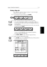
Page 107: ...key pressesrequiredto perform particulartasks A typical chartplotter screen image is shown for each task The scenarios assume you have read the previous sections of this chapter and that you are famil...

Page 108: ...755 and L760 Fishfinder Place and Goto a Waypoint Place and Goto a Waypoint 1 Press MARKS 2 Position Cursor as required Press the soft key 1 2 3 Press the soft key to go to the waypoint selected by th...

Page 109: ...3 Getting Started Adjusting the Display 3 33 Place and Goto a Waypoint 4 The vessel navigates towards the target waypoint See 5 3 Working wth Waypoints Go to an Individual Target Point on page 5 27 D...

Page 110: ...SCREEN ROUTE FIND SHIP MAKE ROUTE EDIT ROUTE CLEAR ROUTE MORE 2 2 Press the soft key 1 3 4 Press the soft key D4268 1 Press the soft key 1 Position Cursor in this example over an existing waypoint Po...

Page 111: ...T XTE WAYPOINT ADVANCE STOP FOLLOW GOTO SCREEN ROUTE FIND SHIP 7 5 6 8 Press the soft key D4268 3 Press the soft key Press the soft key The route becomes the current route The vessel starts to navigat...

Page 112: ...D SHIP MAKE ROUTE EDIT ROUTE CLEAR ROUTE MORE 2 3 2 Press the soft key 1 4 5 Press the soft key Press the soft key D4269 1 Press the soft key 1 Use the trackpad to move selection bar over required rou...

Page 113: ...Passage Plan 6 Change the TIME to HOURS the display indicates it will take 32 minutes to reach the destination You can change the PLANNED SOG the display updates to indicate TIME required at the plan...

Page 114: ...3 38 HSB Series L755 and L760 Fishfinder Review Your Passage Plan...

Page 115: ...he transducer sends high frequencysoundwaves downintothewater thesesoundwavesstrikefish thebottom orotherobjects in the water and return as echoes The fishfinder interprets these echoes to present an...

Page 116: ...h Several arches together show a school of fish Figure Figure 4 1 illustrates some typical fish indications Figure 4 1 Fish Indications Effect of Frequency and Boat Speed The return from a fish has a...

Page 117: ...or coral produces a complex display the bottom image is irregular with long tails pointing upward A wreck produces a similar image A softer bottom or abottom covered withseaweed producesa wide line a...

Page 118: ...y is displayed 2 Press the WHT LINE soft key to toggle the white line feature ON or OFF Adjusting Display Gain Sensitivity The fishfinder provides controls for GAIN COLOR GAIN and STC These controls a...

Page 119: ...gray L755 or seven colors L760 per palette are available and the echo strengths are divided into three L755 or seven L760 bands to correspond with each shade of gray color The COLOR GAIN control sets...

Page 120: ...on asplitfrequency display press the GAIN ADJUST softkey to select the required frequency for adjustment Note On a single frequency display you adjust the gain for the displayed fre quency 3 If neces...

Page 121: ...pera ture graph speed through water and depth Data Window B provides position course over ground COG speed over ground SOG and depth Data Window C provides waypoint range and bearing course over groun...

Page 122: ...than that set the buzzer sounds and a pop up win dow describing the alarm is displayed Youcannotset the shallow alarm to be deeper than the deep alarm Deep water You set depth at which the deep water...

Page 123: ...at The VRM variable range marker key is used on the Fishfinder to determine the depth and distance behind boat of an object on the display The VRM functionis available on thescrollingfishfinder displa...

Page 124: ...e position an off screen VRM 1 Press VRM EBL The VRM is displayed in its last used position The cursor is positioned at the center of the crosshair and has control of the VRM asindicatedbyfour wayarro...

Page 125: ...m Zoom and Bottom Lock displays The waypoint number is shown at the top of the vertical line The waypoint scrolls to the left with the scrolling bottom display If you place a waypoint at the cursor po...

Page 126: ...Waypoint List and named with the next available number To return to the default soft key display press ENTER or CLEAR three times To GOTO a cursor waypoint see Going To an Individual Target Point on p...

Page 127: ...cal line and the letter MOB Marks the current position on the chart display with a MOB symbol Displays the MOB data box showing the bearing and distance from your vessel to the MOB waypoint position a...

Page 128: ...4 14 HSB Series L755 and L760 Fishfinder MOB...

Page 129: ...including measuring distances and setting alarms are described in Chapter 6 Safety The chartplotter makes it very easy to place a waypoint and travel towards it However you should always check first t...

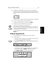
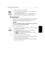
Page 130: ...he screen to the bottom of the screen Note You can remove and insert cards while a chart is displayed The chart information is retained on screen until the chartplotter redraws the screen for example...

Page 131: ...hat it clicks shut to prevent water from entering the card reader assembly Displaying the Chart Data Thenewchartinformationwillbedisplayedwhenyoumove thecursorintoan area covered by the new chart or i...

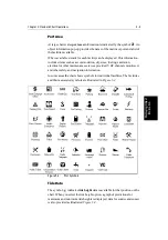
Page 132: ...play detailed information To obtain the chart object port or tide information 1 Move the cursor over the symbol for which you require the information An Object data box such as the following is displa...

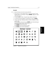
Page 133: ...eling sanitation electrical or other maintenance services provided VHF channels monitored and other safety and navigation information In some areas the chart shows symbols for individual facilities Th...

Page 134: ...de information is shown Figure 5 3 Tide Data To select a time use the trackpad to move the cursor to the required time To change the day press PREV DAY DAY or TODAY as required Alternatively press SET...

Page 135: ...oft key The port facility symbols are displayed 3 Use the trackpad to highlight the required facility then press ENTER 4 The nearest ports providing that facility are listed with distance and bear ing...

Page 136: ...oucanplacewaypoints usingsimulator mode before you install the chartplotter on your vessel Note Radar marks may also be displayed onthe screen ifyour chartplotter is part of an integrated system these...

Page 137: ...ss CLEAR You can use the EDIT WAYPOINT soft key to name the waypoint as described in Editing Waypoints below 2 Press CLEAR or ENTER to remove the place waypoint soft keys To place a waypoint using the...

Page 138: ...tDataDisplayonpage 5 10 andthe following soft keys are displayed The selected waypoint can be edited via these soft keys To select a waypoint using the Waypoint List 1 Press MARKS followed by the WAYP...

Page 139: ...ow Temperature depth date and time are included if available for waypoints placed at the vessel position To remove the Waypoint List and return to the default soft key display press CLEAR twice Editin...

Page 140: ...trackpad to scroll through the characters Adjust each parameter until the waypoint position is correct Whenyouhave finishededitingtheposition pressENTERto save the position or CLEAR to cancel the ope...

Page 141: ...editingwaypoints asit is possible to move waypoints that are used in routes stored in the Route Database List To move a waypoint using the cursor 1 Move thecursor over thewaypoint untilthelettersWPTa...

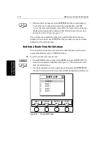
Page 142: ...to 20 routes can be saved in the route database You can then select a route from the database list as the current route The currentroute can be edited by adding and moving waypoints The current route...

Page 143: ...new route by placing waypoints Note You can pan the chart and change the scale while placing waypoints 1 If necessary move the cursor to the area in which you wish to make the route and select a suita...

Page 144: ...the route as described below Note The completed route is stored in the display unit and will be re dis played if you turn the unit off and on again However on an integrated system it is possible for a...

Page 145: ...he operation To return to the default soft key display press ENTER again Clearing the Current Route Youcanclearthecurrentroute fromthescreen WhenyouselectCLEARROUTE if the current route has not been s...

Page 146: ...route or to show another route from the database Retrieve a Route From the Database You can select a route as the current route from the database list The list is accessed from the second set of ROUTE...

Page 147: ...The waypoint data box is displayed this box includes the route and waypoint number To remove the data box move the cursor away from the route or press CLEAR Using Route Information to Review Your Pass...

Page 148: ...allow you to toggle between ETA or total elapsed time and to change the Speed Over Ground SOG value used in the time calcu lations The current selections are highlighted To change the SOG used for ETA...

Page 149: ...TER or CLEAR if you wish to remove the route list Press YES to erase the route from the list then ENTER or CLEAR to remove the route list 3 If youNAME a route use the trackpad to move the cursor right...

Page 150: ...on The new waypoint is temporarily added to the waypoint list and named with the first available waypoint number The waypoints in the current route are re numbered to identify the new positions Note I...

Page 151: ...from a route by pressing the UNDO WAYPOINT soft key as describedabove in Adding Waypoints at the End of the Route on page 5 22 If the route has not been saved the waypoint is erased If the route has...

Page 152: ...luding joining at a selected waypoint advancing waypoints and restarting XTE Go to an individual point either an existing waypoint or the cursor Stop and Restart Follow Goto An alarm is triggered when...

Page 153: ...ress the ROUTE default soft key followed by MORE The route soft keys are displayed 2 Press the REVERSE ROUTE soft key The current route is reversed on the screen Press ENTER or CLEAR 3 Press the GOTO...

Page 154: ...entleg Anyprevious route leg is removed from the screen but waypoints remain Note Whenfollowing arouteusinga SeaTalk autopilot the autopilotwill not turn to the new waypoint until it is accepted at th...

Page 155: ...ff track and want to go straight to your target rather than get back onto the original track To restart XTE 1 Press the GOTO default soft key the Follow Goto soft keys are displayed 2 PresstheRESTARTX...

Page 156: ...vessel s starting position with a dashed line The soft key STOP GOTO is displayed Note The temporary waypoint is not added to the waypoint list when the GOTO is complete or is stopped the temporary wa...

Page 157: ...transmitted by other equipment on SeaTalk or NMEA you can receive them on the chartplotter When this optionisselected anywaypoints sent on SeaTalk or NMEA are transferred and appended one by one to t...

Page 158: ...STOP SENDING WAYPOINTS The waypoint and route lists are transmitted from the chartplotter to other instruments on NMEA To receive the waypoint and route lists via HSB CAUTION Copying waypoints from a...

Page 159: ...ater date For example you may wish to display a previous track and then place waypoints along it that you can follow You can only display one track at a time you must clear a current track from the sc...

Page 160: ...nt Track You can clear the current track from the screen When you select CLEAR TRACK if the currenttrack has notbeensaved youhave the option of saving it To clear the current track 1 Press the CLEAR T...

Page 161: ...Then use the top or bottom of the trackpad to increase or decrease the letter or number 5 Press ENTER to finish and clear the Track List then to return to the default soft key display press ENTER aga...

Page 162: ...ou SHOW a track and you have a current track on screen you are promptedtosavethetrack ProceedaspreviouslydescribedinClearingthe Current Track Alternatively press the NO soft key to cancel the SHOW TRA...

Page 163: ...ional datafrom equipmentconnectedtoyoursystem via aHSB SeaTalk or NMEA link If headingdataisavailableviabothNMEA andSeaTalk NMEAdata takespriority Forallotherdata SeaTalk data takes priority see Secti...

Page 164: ...Ruler data box is displayed showing the bearing and distance from the starting point to the cursor position The character A appears at the cursor location 3 Use the trackpad to move the cursor to the...

Page 165: ...to the previous position To clear the ruler line and ruler data box either Move the cursor over the ruler line until the letters A B are displayed then press CLEAR or Press VRM EBL the ruler soft keys...

Page 166: ...larms are switched on or off and the limits set using the Alarms Set Up menu accessed from the ALARMS key When an alarm is triggered the alarm buzzer sounds and a pop up window describing the alarm is...

Page 167: ...imer is set in hours minutes and seconds and the alarm clock in hours and minutes 4 If required press the ALARM OFF ON soft key to toggle the alarm on or off If youturn analarm off its valueisretained...

Page 168: ...rawsthe chartat1 2nm evenifcartographyisnotavailablebutplotter mode is on Marks the current position with a MOB symbol which replaces any current active waypoint and route Displays the MOB data box sh...

Page 169: ...options can be toggled ON or OFF Radar Cursor In displays the cursor from another radar on the chart dis play or chart window default OFF Chart Cursor In displays the cursor from another or chartplott...

Page 170: ...To tune a differential SeaTalk GPS to another beacon 1 Press D GPS SETUP the Differential GPS Setup pop up is displayed with MODE and BEACON SELECT soft keys 2 Press MODE AUTO MAN to toggle the GPS t...

Page 171: ...ood CMG since last log entry Distance Made Good DMG since last log entry Once you have enabled the data log data is continually logged but you must set the display to Data Log Mode to view it You use...

Page 172: ...y Press DISPLAY to select the chart mode then press ENTER The log continues until you return to the data log mode and press STOP LOG TIME POSITION CMG DMG CLEAR LOG STOP LOG 15 30 16 00 16 30 17 00 17...

Page 173: ...set up your system However you may decide to change the way you have customized some aspects such as the screen and help setting as you become more familiar with your system Onceyouhavesetthevalues th...

Page 174: ...n of each parameter in turn To set the default parameters 1 Press the MENU key to display the set up soft keys The options available depend on the selected operating mode Fishfinder Chart 2 Press the...

Page 175: ...move the selection bar on to the next parameter in the menu list For sliders press the appropriate soft key repeatedly to increase or decrease the slider value in individual steps or press and hold t...

Page 176: ...TDs OFF or ON OFF or ON OFF or ON OFF or ON OFF or ON OFF or ON OFF APP TRUE or BOTH OFF LAT LON or RNG BRG TTG OFF or ON OFF or ON OFF or ON OFF or ON OFF WIND WPT or BOTH OFF or ON OFF or ON OFF OFF...

Page 177: ...at most of the picture can still be seen The ones you select here can be turned on and off as a groupduringnormaloperation andyoucanalsomovethem aroundthescreen individually using the context sensitiv...

Page 178: ...the heading value in the status bar at the top of the screen Cursor Readout This optioncontrolswhether thecursor data isshowninlatitude andlongitude or in range and bearing Alternatively you can show...

Page 179: ...t menus and soft key labels remain displayed until you clear them by pressing ENTER CLEAR or the appropriate dedicated key Ifyousetavalue here themenusandsoftkeylabelswillbeclearedifakeyhas not been p...

Page 180: ...d no position data is available Manual Mode If you select Manual mode by pressing either of the MANUAL keys you can specify the local variation value according to the area in which you are operating P...

Page 181: ...to display the cursor transfer soft keys The following options can be toggled ON or OFF Radar Cursor In displays the cursor from another radar on the chart dis play or chart window default OFF Chart C...

Page 182: ...isplayed during operation showing the simulation selected Fishfinder simulator mode is set in the Sonar setup menu described in Section 7 4 7 4 Fishfinder Set Up Parameters The SONARSET UP optionallow...

Page 183: ...to a Fishfinder master display Depth data is sourced from a master display Depth Offset The depth offset is added to the measured depth value before it is displayed You can specify the depth as a posi...

Page 184: ...Temperature Calibration to a positive value If the Fishfinder reading is to high set Temperature Calibration to a negative value Sonar Simulator The simulator allows you to operate your display withou...

Page 185: ...ed between on off and custom custom passes on off control to the SCREEN soft keys see Customizing the Screen Presentation Options on page 3 25 The following features can be set using Customize Chart f...

Page 186: ...n is normally North Up but can be changed to Course Up or Head Up if heading data is available The orientation modes give the following displays North Up The chart is displayed with north upwards As y...

Page 187: ...ime period An infinite vector extends to the edge of the chart screen Heading Vector indicates your current heading COG Vector indicates your course over ground Tide Vector indicates the tide angle Ti...

Page 188: ...n offset on off 1 Select the POSITION OFFSET option then press the OFFSET OFF ON soft key to toggle the option on off The last selected offset value is added to posi tion data and the vessel is displa...

Page 189: ...e procedures are therefore limited to the following periodic checks Examine the cables for signs of damage such as chafing cuts or nicks Check that the cable connectors are firmly attached Cleaning In...

Page 190: ...ct performance There are no user serviceable parts in any Raytheon product Some products generate high voltages so never handle the cables connec tors when power is being supplied to the equipment Whe...

Page 191: ...icture of the top window with all windows cleared At power on the last used values are retained for all the options except for those listed in the following table which are reset to the factory defaul...

Page 192: ...ero 2 Check the transducer cable for damage If damaged the cable and transducer must be replaced as a unit Fishfinder does not see bottom or fish 1 If you have a transom mount transducer check that th...

Page 193: ...er If you are not sure which item is appropriate for your unit you should first contact the Technical Support Department at 1 800 539 5539 ext 2444 or 603 881 5200 to verify your requirements For Tech...

Page 194: ...dy when you call We will do everything possible to make the repair and return your unit as quickly as possible How to Contact Raytheon Europe In Europe Raytheon support service and accessories may be...

Page 195: ...rs and optional accessories in the Installation chapter of this manual and have the Raytheon part number ready when speaking with your dealer If you are uncertain about what item to choose for your Ra...

Page 196: ...8 8 HSB Series L755 and L760 Fishfinder Worldwide Support...

Page 197: ...olated 20 W max consumption with full brightness Environmental Operating Storage Temp Range Mono Color Humidity limit Waterproof to CFR46 suitable for external mounting 10 C to 70 C 10 C to 50 C up to...

Page 198: ...t shows range bearing lat lon of MOB and time elapsed since MOB Screen Functions Full half and quarter screens available dependent on function Data Boxes Up to six user selectable information boxes Ou...

Page 199: ...countdown timer and alarm clock Navigation Information Own ships position in Lat Lon XTE TTG and SOG COGselectable Mileagescaleruler Bearinganddistancetowaypoint Bearingand distance to cursor SeaTalk...

Page 200: ...A 4 HSB Series L755 and L760 Fishfinder Appendix A Specifications...

Page 201: ...round information to the HSB displays is by connection to a SeaTalk GPS The HSB series chartplotter displays are supplied with an AuxiliaryJunction Box whose mainpurposeistomakethisconnectioneasier Th...

Page 202: ...f the 5 pin connector Raytheon and Apelco versions stripbackthe insulation on all the wires and connect to the Auxiliary Junction Box as shown in the second illustration below CAUTION Ensure the corre...

Page 203: ...k the insulation on all the wires and connect to the Auxiliary Junction Box as shown in the second illustration below CAUTION Ensure the correct polarity of the 12 V supply before applying display or...

Page 204: ...es Remove the sleeve from the end of the Raystar 112LP cable toexpose the green and brown wires then connect to the Auxiliary Junction Box as shown in the second illustration below CAUTION Ensure the...

Page 205: ...p back the insulation on all the wires and connect to the Auxiliary Junction Box as shown in the illustration below CAUTION Ensure the correct polarity of the 12 V supply before applying display or Se...

Page 206: ...B 6 HSB Series L755 and L760 Fishfinder Appendix B Using the Auxiliary Junction Box...

Page 207: ...M soft key to switch the customized icons off on The factory default for the CUSTOM options is on The chart features controlled from the Customize Chart menu are grouped as detailed below some groups...

Page 208: ...ritorial sea baseline Submarine transit lane Territorial sea area Restricted area Sea Plane landing area Military practice area Tracks and Routes Deep water route part Deep water route cen terline Fai...

Page 209: ...Lake Lake shore Cultural Features Airport area Built up area Railway Road crossing Road part Runway Sloping ground Square Cable overhead Fence Pipeline overhead Pylon Telepheric Tunnel entrance Buildi...

Page 210: ...escue station Signal station traf fic Signal station warning Port Information Port area Harbour master Coast Guard Police Customs Health emergency Post office Yacht club Boat yard Accessories Electric...

Page 211: ...Production installation Offshore platform AREAS LIMITS No data area CARTOGRAPHIC OBJECTS Incomplete survey area NATURAL FEATURES Ice Ice area Pingo COMPOSITE OBJECTS Airport Anchorage Channel edge De...

Page 212: ...C 6 HSB Series LCD Color Display Appendix C C MAP Chart Card Features...

Page 213: ...B XTE Depth SeaTalk DBT DPT Apparent Wind Angle and Speed SeaTalk MWV relative Boat Speed Through Water SeaTalk VHW Total Log and Trip Log SeaTalk VLW Water Temperature SeaTalk MTW Average Boat Speed...
Page 214: ...Bridged from NMEA if selected in the System Set Up menu Data Output SeaTalk NMEA Out Position LAT LON GGA GLL RMC1 RMA Position Loran C TD s RMA Speed Over Ground and Course Over Ground RMC VTG1 RMA W...

Page 215: ...und CRT Cathode Ray Tube CTR Center dB deciBels DC Direct Current DMG Distance Made Good DR Dead Reckoning EBL Electronic Bearing Line EMC Electro Magnetic Compatibility ETA Estimated Time of Arrival...

Page 216: ...erBoard MRK Mark nm nautical mile NMEA National Marine Electronics Association POS Position of vessel RF Radio Frequency Rng Range rpm Revolutions Per Minute SSB Single Side Band SHM Ships Heading Mar...

Page 217: ...Tide 5 4 5 5 Definition 1 2 Mode 1 4 1 5 Full Screen 3 9 Moving 3 27 Orientation 7 13 7 14 Course Up 7 14 Head Up 7 14 North Up 7 14 Scale 3 27 5 2 5 15 6 6 Set Up Radar Chart Synch 1 10 7 13 Simulat...

Page 218: ...nd 7 4 XTE 7 4 Data Display 5 19 Chart Object 5 4 Nearest 5 7 Port 5 4 5 5 Tide 5 4 5 5 Fishfinder 4 7 Route 5 15 Data from other Equipment 2 44 4 13 6 1 6 6 COG 6 1 Heading 4 13 6 1 6 6 NMEA 6 1 Posi...

Page 219: ...k 3 20 White Line 4 1 4 4 Zoom 1 8 3 23 Echoes 1 6 3 6 Features 1 6 A 3 Functions 1 8 HSB Mode 7 10 7 11 Mode 1 5 3 2 Full Screen 1 4 3 9 Set Up 7 2 7 10 Simulator 3 1 3 5 7 10 7 12 Window Options 1 5...

Page 220: ...intenance 8 1 Make and Follow a Route Scenario 3 34 Man Overboard MOB See MOB Managing Tracks 5 31 Marks 5 8 MARKS Key 1 15 4 11 4 13 5 9 5 10 5 29 6 6 Master Display 1 3 2 36 5 2 Definition 1 2 Measu...

Page 221: ...1 2 Radar Mode 1 5 Radar Repeater 1 2 Radar Chart Synchronisation 7 13 Range Fishfinder 3 18 RANGE Key 1 15 3 18 3 28 3 29 5 2 Remote Cursor Echo Chart 6 7 7 9 Radar 6 7 7 9 Removing a Waypoint from a...

Page 222: ...ronize Chart and Radar 1 10 7 13 System Connections 2 30 Grounding 2 30 Set Up 7 2 T Target Chart 5 24 Arrival 5 24 Goto 5 24 Waypoint 5 24 Target Depth ID 7 10 7 11 Temperature Calibration 7 10 7 11...

Page 223: ...ion 5 8 5 11 Removing from a Route 5 15 5 23 Selecting 5 8 Symbol 5 8 5 11 7 13 7 15 Target 5 24 Transfer 5 8 5 14 Transferring on NMEA 5 29 Transferring on SeaTalk 5 29 White Line 4 1 4 4 Wind Data B...

Page 224: ...viii HSB Series L755 and L760 Fishfinder...

Reviews: