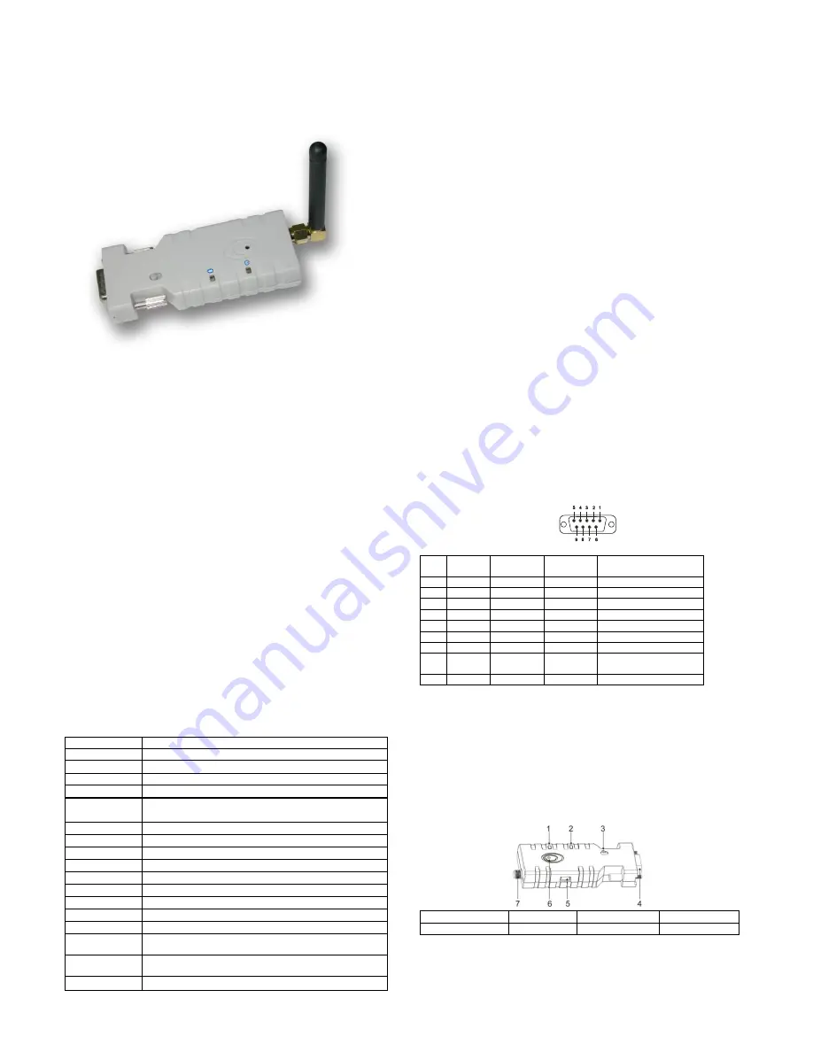
Bluetooth Serial Adaptor
User’s Manual
Wireless Solutions in Your Hand
TABLE OF CONTENTS
1. INTROD
UCTION…………………………………………………3
1.1. Features………………………………………………………… 3
1.2. Package……………………………….…………...……………3
2. SPECIFICATIONS……………………………………….……...3
2.1. Gener
al………………………...……………………………….3
2.2. RS232 Interface
………………….........................................4
2.2.1. Pin-
out………………………………………………………4
2.2.2.
Signals………………………….....................................4
2.3. Factory Settings………………………………………..............4
3. IN
STALLATION……………………………………………………4
3.1. Hardware Structure...
…………………………………………..4
3.1.1. Reset Button……………………………………………..4
3.1.2. Slide Switch ………………………………………………4
3.1.3. Power Supply …………………………………………….5
3.1.4. LED Status……………………………………………..... 5
3.2 Installation
Procedure………………………………………….5
4. USAGE…………………………………………………………….5
4.1 HyperTerminal Settings………………………………………..5
4.2 Configuration…………….……………………………………..5
4.2.1. Configuration Start-up
…………………………………..5
4.2.2. Master Role Configuration
………………………………6
4.3 AT Command
Set………………………………………………6
-
2
-
1. Introduction
Thank you for purchasing our Bluetooth serial adaptor. The adaptor eliminates
your conventional RS232 serial cables, providing an easy-to-use, invisible
connection with superior freedom of movement. This tiny adaptor allows any
device with a standard 9-pin serial port to communicate wirelessly. You can
communicate with another
Bluetooth
serial adaptor or other
Bluetooth
-enabled
devices such as a laptop computer, PDA or mobile phone.
1.1. Features
Supports Bluetooth Serial Port Profile and Generic Access Profile
No need of external host and software
Easy of installation and use
Supports configuration of the local device
Easy of maintenance
Supports up to 100 meters (line of sight)
1.2. Package
Bluetooth serial adaptor: 1 ea
Antenna: 1 ea
DB9 male to female converter: 1 ea
USB cable for power supply: 1 ea
DC adaptor: 1 ea
U
ser’s manual: 1 ea
2. Specifications
2.1. General
Specification
Description
Baud Rate
Supports 4.8/9.6/19.2/38.4/57.6/115.2/230.4 Kbps
Coverage
Up to 100 m
Connection
Point-to-point (pico net)
Signal
TxD, RxD, GND, CTS, and RTS
RS-232
Interface
D_SUB 9-pin female
Standard
Bluetooth specification version 2.0+EDR
Frequency
2.400 to 2.4835 GHz
Hopping
1,600/sec, 1MHz channel space
Modulation
GFSK-1 Mbps, DQPSK-2 Mbps, and 8-DPSK-3 Mbps
Tx. Power
Max. 18 dBm (Class 1)
Rx. Sensitivity
-86 dBm typical
Antenna
Chip antenna or SMA external antenna (optional)
Antenna Gain
Chip antenna max. 1 to 2 dBi
Power Supply
+5 to +6 V DC
Current
Consumption
Max. 90 mA
Operation
Temperature
-
20°C to +75°C
Dimensions
35 mm (W) x 65 mm (D) x 16 mm (H)
-3 -
2.2. RS232 Interface
2.2.1. Pin-out
2.2.2. Signals
Pin
Signal
DTE
Direction
DCE
Direction
Description
1
CD
Input
Output
Not connected
2
TxD
Output
Input
Transmitted data
3
RxD
Input
Output
Received data
4
DSR
Input
Output
Not connected
5
GND
N/A
N/A
Signal ground
6
DTR
Output
Input
Not connected
7
CTS
Input
Output
Clear to send
(Remarks)
8
RTS
Output
Input
Request to send
(Remarks)
9
Vcc
Input
Input
Power supply
Remarks: The default hardware configuration is for using CTS/RTS. If you want to
use DSR/DTR, please contact us.
2.3. Factory Settings
The factory settings of COM port are as follows:
Baud rate: 19200 bps
Data bit: 8
Parity: none
Stop bit: 1
Flow control: H/W or none
Others: Please refer to section 4.3 AT Command Set.
3. Installation
3.1. Hardware Structure
The figure below is an outline of the adaptor.
1 Power LED
2 Link LED
3 Slide switch
4 RS232 connector
5 Mini USB Connector
6 Reset button
7 Antenna connector
3.1.1. Reset Button
By pressing the Reset button, you can:
Disconnect and reconnect a wireless connection (after a short press)
.
Restore the factory settings (after over three seconds' press).
3.1.2. Slide Switch
The slide switch can swap TXD/RXD and CTS/RTS signals.
By switching, you can set the adaptor either as a DTE (towards antenna connector)
or a DCE (towards RS232 connector).
- 4 -


