4.8 Testing the transducer
Once the initial mounting procedures have been
carried out, the transducer must be tested prior to
inishing the mounting.
The testing should be carried out with your vessel in
the water, with a depth greater than 0.7 m (2.3 ft) but
less than the maximum depth limit of the system.
The Sonar application will be able to maintain
readings at depths greater than the DownVision
application.
Note:
It may not always be possible to obtain
depth readings at higher speeds due to air bubbles
passing under the transducer.
1. Press and hold the
Power
button until a beep is
heard.
2. Complete the Start-up wizard settings.
3. Use the View switcher to open a view which
contains the Sonar or DownVision application.
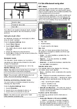
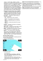
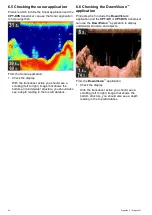
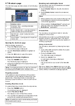
If the unit is operating correctly the bottom should
be visible on-screen and the depth reading
displayed.
4. Start moving your vessel at a low speed and
ensure the depth reading and bottom are shown
and that you have a clear image on-screen.
5. Gradually increase the vessel speed up to your
usual cruising speed, whilst checking the display
if the image becomes poor, starts skipping or
missing the bottom then the transducer needs
to be adjusted.
6. Height and angle adjustments should be made in
small increments, and re-tested each time until
you obtain optimum performance.
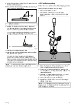
7. To adjust the angle of the transducer loosen the
pivot bolt approximately 3 turns and then pivot
the transducer either up or down.
8. Re-tighten the pivot bolt before re-testing.
9. When you achieve optimum performance at
the desired vessel speeds you can inish the
transducer mounting.
Note:
It may be necessary to make several
adjustments to the transducer before obtaining
optimum performance.
4.9 Finishing the transducer mounting
Once you have achieved optimum performance at
the desired vessel speeds the transducer must be
locked into position to inish the installation.
Note:
If the transducer requires repositioning
ensure all old holes are illed with marine grade
sealant.
1. Loosen the kick-up adjustment screw.
2. Lift up the transducer and bracket pivot arm to
gain access to the mounting holes.
3. Drill the locking hole location taking care not to
damage the mounting bracket.
4. Fill the locking hole with marine grade sealant.
5. Secure the transducer and bracket by fully
tightening all 3 mounting screws.
6. Push the transducer and pivot arm down until it
clicks into position.
7. Re-tighten the kick-up adjustment screw to the
desired level.
Note:
The Kick-up adjustment screw needs to be
tight enough to prevent kick-up during high speeds
but loose enough to enable the kick-up feature
to activate if an object hits the transducer when
underway.
32
Dragonly 6 / Dragonly 7
Summary of Contents for Dragonfly 6
Page 2: ......
Page 4: ......
Page 24: ...24 Dragonly 6 Dragonly 7...
Page 82: ...82 Dragonly 6 Dragonly 7...
Page 96: ...96 Dragonly 6 Dragonly 7...
Page 104: ...104 Dragonly 6 Dragonly 7...
Page 108: ...108 Dragonly 6 Dragonly 7...
Page 112: ...112 Dragonly 6 Dragonly 7...
Page 115: ......
Page 116: ......

