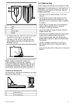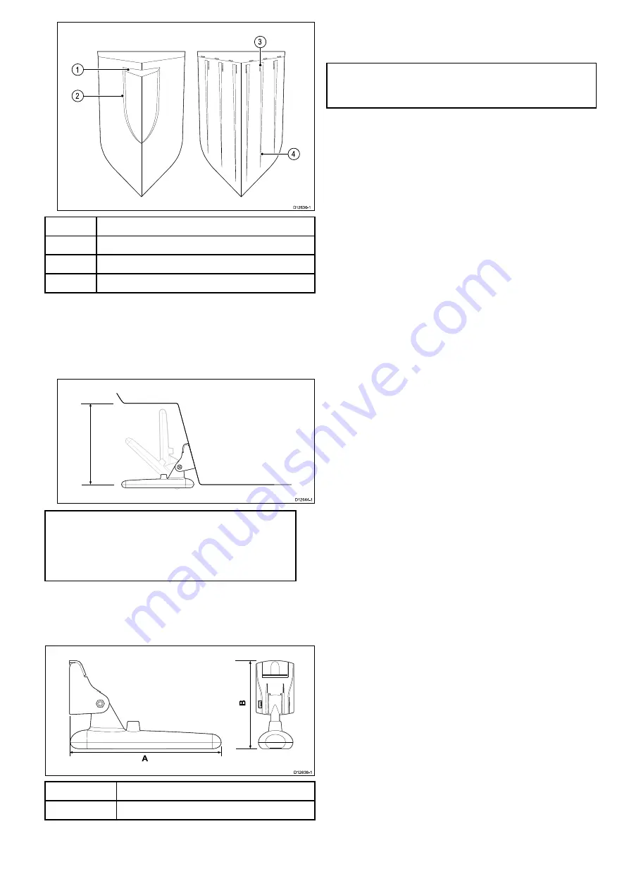
1
Step
2
Rib
3
Row of rivets
4
Strake
• Air trapped under the front of the vessel can travel
under the hull and appear as aeration aft.
• If installing on the step of a stepped transom,
allow sufficient room above the transducer for
transducer kick-up.
Note:
Optimum transducer location will
vary depending on vessel type. Optimum
transducer height and angle should be obtained
by testing the transducer with the vessel in the
water before locking the transducer’s position.
Transducer dimensions
The transducer’s dimensions including the mounting
bracket are shown below.
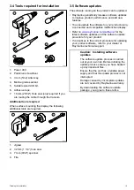
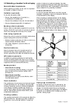
A
202.6 mm (8 in)
B
117.4 mm (4.6 in)
3.8 Cable routing
Cable routing requirements for the transducer cable.
Important:
To avoid interference, the cable must
be routed as far away from VHF radio antenna
cables as possible.
• The cable can be routed through or over the
transom.
• Check that the cable is long enough to reach
the equipment that it will be connected to. An
optional 4 m (13.1 ft) extension cable is available
if required.
• Ensure there is enough slack in the transducer
cable, at the transducer end, to allow the
transducer to pivot up and down.
• Secure the cable at regular intervals using the
supplied cable clips.
• Fill all transom mounting holes with marine-grade
sealant prior to tightening securing screws.
• Fill the transom cable hole with marine-grade
sealant after routing the cable (if routing through
the transom).
• Use the supplied escutcheon to cover over
the transom cable hole (if routing through the
transom).
• Any excess cable can be coiled up at a convenient
location.
Planning the installation
21
Summary of Contents for Dragonfly 6
Page 2: ......
Page 4: ......
Page 24: ...24 Dragonfly 6 Dragonfly 7...
Page 82: ...82 Dragonfly 6 Dragonfly 7...
Page 96: ...96 Dragonfly 6 Dragonfly 7...
Page 104: ...104 Dragonfly 6 Dragonfly 7...
Page 108: ...108 Dragonfly 6 Dragonfly 7...
Page 112: ...112 Dragonfly 6 Dragonfly 7...
Page 115: ......
Page 116: ......

