background image

MT5 Multi-Tracer Operating Manual 

page 9 


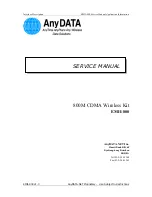
Figure 1. Grounding lug. 

Raydec recommends connecting the largest gauge wire possible in your installation 

from this external ground point to earth ground. Note: That this external ground is not 

needed for proper operation, nor is the unit unsafe without this connection. However, 

this connection provides additional safety if the MT5 Load Unit experiences a 

catastrophic failure requiring that all module currents be shunted to ground.  

Summary of Contents for MT5

Page 1: ...MT5 Multi Tracer Operating Manual Raydec Inc 10255 Corona Ave NE Albuquerque NM 87122 Doc Version 2 04 Jan 2022 505 292 5002 info raydec com www raydec com ...

Page 2: ... 4 Connections 10 Load Control 10 PV Module Connections 11 Wire Size and Voltage Drop 14 Aux Input Connections 15 Thermocouple Connections 16 Keyboard and Video Monitor 17 3 1 5 Power Up 18 3 1 6 Network 18 3 1 7 Setting the Time 18 4 MT5 System Configuration and Use 19 4 1 Real Time Data Tab 20 4 2 IV Curve Data Tab 21 4 3 Settings Tab 22 4 3 1 Global Load IV Curve Control 22 ...

Page 3: ...Aperture Total Area 27 Advanced Power Tracking 27 Associated Temperatures Irradiance and Aux Data 28 4 3 3 Aux Input Scales 31 4 3 4 Temperature Setup 33 4 3 5 IV Curve Setup 34 4 3 6 Data Logging 35 4 4 System Tab 36 4 4 1 Date Time 36 Manual Time Date 36 Automatically Set Time 37 4 4 2 Network Settings 39 4 4 3 Users 40 4 4 4 Calibration 40 4 5 Help Tab 41 4 6 Direct Hardware Interface 43 5 Mult...

Page 4: ...rk Change via Temporary Network 51 6 2 Testing Network Connection 53 6 3 Advanced Network Settings 55 6 3 1 Gateway Address 55 6 3 2 DNS 1 2 55 6 3 3 MAC Address 55 6 4 Network Security Usernames and Passwords 56 6 4 1 Web Interface Access Control 56 6 4 2 FTP Access 58 6 4 3 Resetting Passwords 59 6 4 4 Security Limitations 59 7 Calibration 60 7 1 Module Voltage Calibration 61 7 2 Module Current ...

Page 5: ... 1 Connecting a new load 72 10 2 Learning The System Configuration 73 10 3 Show System Configuration 74 11 Maintenance 75 11 1 MT5 Controller 75 11 1 1 MT5 Load Unit 75 Appendix A Multi Tracer Connectors 78 Appendix B Peak Power Tracking 79 Appendix C Module Fuse Replacement 81 Appendix D Replaceable Parts 83 Appendix E Specifications 84 Appendix F Network Access and Ports 88 ...

Page 6: ...e each hour An MT5 System consists of one MT5 Controller and one to four load units An MT5 Controller operates the load units and also samples data from the temperature and auxiliary input connections A standard MT5 Controller has 24 temperature thermocouple inputs and 8 Aux inputs An MT5 Load Unit provides an electrical load and data acquisition for up to 16 photovoltaic PV modules The actual loa...

Page 7: ...detail in the following sections 3 1 Hardware Installation Follow these basic steps for proper installation 1 Mount the MT5 Controller and Load Unit s 2 Connect AC power but leave units turned off 3 Connect MT5 Load unit s to MT5 Control Unit using provided cable 4 Connect PV modules temperature sensors and other signals 5 Power up the MT5 Load and Control units 6 Allow approximately 2 minutes for...

Page 8: ...er Both the MT5 Controller and Load units require AC power Raydec strongly recommends powering the MT5 Controller and Load units through an uninterruptible power supply UPS The MT5 System includes an internal computer and as with any computer clean and stable power helps to ensure trouble free operation In addition to helping to prevent system damage a UPS also reduces the possibility of losing da...

Page 9: ...nstallation from this external ground point to earth ground Note That this external ground is not needed for proper operation nor is the unit unsafe without this connection However this connection provides additional safety if the MT5 Load Unit experiences a catastrophic failure requiring that all module currents be shunted to ground ...

Page 10: ...to the load on the air conditioning system This will require the cooling system work harder to remove this heat from the room Or conversely this heat will help warm a room in winter months The MT5 load dissipates all of the PV module power as warm air plus some small additional power from the load unit circuitry The MT5 Control unit dissipates little power and no special precautions or ventilation...

Page 11: ...nnector for each PV module input The connector and each pin function is shown in Figure 2 Vsense Vsense PV GND PV Figure 2 Multi Tracer PV module input connector Depending on the size of the wires used the module connector strain relief may be attached in one of two positions as shown in Figure 3 ...

Page 12: ... convert the given channel from positive to negative grounding Please see the section 8 Changing Module Grounding for details The module connects to the Multi Tracer in one of two ways either the positive input PV and ground GND or to the negative input PV and ground GND Never connect a module to PV and PV at the same time No damage should result but the unit will not function properly The voltage...

Page 13: ...le wiring for negative grounding Voltage Sense Voltage Sense PV PV Ground PV Module No Connection Figure 5 Multi Tracer PV module wiring for positive grounding Four wires connect the PV module to the Multi Tracer Positive PV Power Lead Large Gauge Negative PV Power Lead Large Gauge Positive Voltage Sense Lead Negative Voltage Sense Lead ...

Page 14: ...e 1 shows the approximate wire resistance for several gauges of wire Note The largest wire the MT5 module connectors accommodate is 10 AWG This is highlighted in the wire table The total wire length is the combined or round trip distance of the positive and negative module power leads As an example the voltage drop at 10 A is shown The significance of this voltage drop is that it limits how close ...

Page 15: ...or each auxiliary Aux input These are typically used for pyranometers but may be used for any DC voltage signal within the input range of 5V The connector and each pin function is shown in Figure 6 Signal 1 Signal 2 GND Shield 3 Figure 6 Multi Tracer Aux input connector Note The Multi Tracer makes a differential measurement between the signal positive and negative inputs However this signal must b...

Page 16: ...per Different grounding schemes may have significant impact on signal noise If noise appears to be a problem try alternate methods of referencing the signal and alternate connections for the signal cable shield Thermocouple Connections The MT5 Controller accepts standard mini thermocouple plugs as shown in Figure 7 Figure 7 Type T Mini thermocouple plug ...

Page 17: ...ontrol unit A computer monitor can be connected to the video port This video port is a standard VGA analog video connector Figure 8 Video and USB Connections Use of the keyboard and monitor is optional and is only necessary for reconfiguring the system as described in section 10 System Expansion and Configuration or as an alternate user interface when changing network settings as described in sect...

Page 18: ...ork connection to the unit This network connection is the primary user interface to the unit Please refer to the section 6 Network Connection for details on setting up and testing the network connection to the Multi Tracer 3 1 7 Setting the Time The first thing to do after getting the MT5 system running and establishing a network connection is to set the system date and time This is done using the...

Page 19: ...formance data under load and IV curves see section 5 Multi Tracer Data A web browser provides the Multi Tracer user interface Currently Mozilla Firefox is the only browser fully compatible with the MT5 system All interface pages have a common layout with menu selection tabs as shown in Figure 9 and Figure 10 Each of these tab menu items are discussed in the following sections Figure 9 Multi Tracer...

Page 20: ... Security Usernames and Passwords for details on users and access control The following descriptions assume no security access limits the default for new MT5 systems or that administrator access is in use 4 1 Real Time Data Tab The Real Time Data tab is the main MT5 data page It shows the latest measurements updated once per second This page only displays data and provides no other features Figure...

Page 21: ...ly take IV curves Figure 13 IV curve data table To take an IV curve of all modules press the Take All Curves button To take selected curves use the check boxes to enable a subset of curves and then press the Take Selected Curves button These settings have no effect on automatic IV curves and are only used to manually take IV curves The Multi Tracer takes manual curves independent of any settings t...

Page 22: ... for continuous load operation and IV curves Figure 14 Global load IV curve modes Global Load Mode This setting controls how all the module loads operate while collecting performance data All Loads Off Turns all loads off open circuit regardless of individual module channel setting All Peak Power Sets all modules to peak power track regardless of module channel setting All Fixed Voltage Sets all m...

Page 23: ... manual IV curves None No automatic IV curves are taken at any time regardless of IV curve or module channel settings All Channels Automatic IV curves are taken on all channels even if these channels are not individually enabled for IV curves Channel Defined IV Curves are taken on modules that have been enabled for IV curves within that module s channel settings ...

Page 24: ... the page opens to the first module in the system Use the Module Channel drop down list to select the specific module to work with Note These settings are optional though important to get the full benefit of the MT5 Figure 15 shows all of the module channel settings Each area of this screen is described below WARNING Press the Apply button to save these settings before moving to another page Figur...

Page 25: ...e module channel number for example 101 as shown below This number uniquely defines the module data But the Description field is recorded in both the MTD performance data files and the IV curves files The System and Site fields are additional description fields These fields are only recorded in the IV curve files and are not recorded in the MTD files Because these fields become part of the data se...

Page 26: ...odule for automatic IV curves See the section 4 3 5 IV Curves Setup for additional details This setting determines if an IV curve is taken automatically for this module when the Global IV Curve Mode is set to Channel Defined See the section 4 3 1 Global Load IV Curve Control for details on overriding this setting Integration Period The Integration Period setting defines the number of microseconds ...

Page 27: ...with an AC power source For example some artificial light sources use AC power with frequencies that cause the light to fluctuate at a frequency of 400 Hz In that case an integration period of 2 500 uS would ideally eliminate the noise at this frequency Aperture Total Area These values are for convenience and are used to calculate the modules electrical efficiency based on the irradiance 1 value a...

Page 28: ...s for example It is therefore unnecessary potentially confusing and a waste of storage space to store all temperature and auxiliary data measurements in every IV curve The association feature defines which temperature irradiance and auxiliary measurements are recorded in a given module s IV curves data file For example the following temperature associations show that system temperature ID 5 labele...

Page 29: ... associated as module temperature numbers 1 2 3 etc in the order they are added using the button However the order can be changed by selecting the associated temperature in the right hand column and using the Move Up or Move Down buttons to alter its association number The Remove button will remove the selected associated temperature The Done button closes this edit box Note These associations mus...

Page 30: ...asuring irradiance However it is common for some auxiliary inputs to be used for irradiance measurements The Associated Aux Irradiance settings associate auxiliary inputs specifically as irradiance measurements This means that these values will be stored as irradiance values in the module IV curve data files This simply identifies the given auxiliary inputs as irradiances values ...

Page 31: ...d the units would typically be in watts per square meter W M 2 However the units field is only a text label and is only informational The units label has no effect on the conversion Another example auxiliary input 2 Wind Speed has converted units of 100 per 4 876 V This could be either 100 miles per hour or 100 m s at 4 876 The converted units depend on the constant applied In this example the uni...

Page 32: ... conversion equation is a standard linear conversion of the form y m x b In this case x Measured voltage m Converted Volts b Offset Recorded Value Measured voltage x Converted Volts Offset For common inputs like those from pyranometers the offset would be 0 However as shown above for the Temp Sensor there is an offset of 25 C In this case the output changes 1 unit 1 C for every 0 01 V 10 mV of sig...

Page 33: ...ture setup page allows the user to name temperature inputs Temperature measurements are not physically associated with any module or temperature source These labels are for convenience Be sure to press the Apply button to save any changes Figure 18 Temperature description setup ...

Page 34: ...during what time period during the day Automatic IV Curves may be scheduled as often as once per minute or at intervals defined in hours and days Furthermore the start and stop times define the time period each day for limiting automatic IV curves For example it is common to limit IV curves to daylight hours Figure 19 IV Curve setup dialog ...

Page 35: ...in a day for recording performance data MTD data The interval represents the average period and time interval between data records recorded in the MTD data file See the section 5 1 Performance Data for details on this data As with all setup pages press the Apply button to save any changes made to these settings Figure 20 Data logging setup dialog ...

Page 36: ...ng its internal clock This clock is similar to those found in a desktop PC The time zone is expressed in hours west of GMT For example in the United States the eastern standard time EST is 5 hours west of GMT while Dubai is 4 hours east of GMT and you would enter 4 for the time zone value No provision is made for automatically handling daylight savings time but the time zone offset can be adjusted...

Page 37: ...work Setting for details Only one NTP time server is absolutely required but up to 4 servers may be specified These can also be given as IP addresses for example 123 145 167 189 Set the MT5 clock manually prior to using the automatic time server This shortens the sync time between time server time and the MT5 clock When using time severs be sure to verify that the MT5 is keeping accurate time If t...

Page 38: ...MT5 Multi Tracer Operating Manual page 38 Figure 22 NTP time server setup dialog ...

Page 39: ...cessing the MT5 from within or outside of the local network changing one or more of these settings may disable your connection Reestablishing a connection may require connecting a keyboard and monitor directly to the MT5 Controller to reset these network settings Refer to the section 6 Network Connection for complete details on the MT5 network connection Figure 23 Network settings IP Address Defin...

Page 40: ...23 123 123 This setting is needed when using NTP time servers defined by name Only one DNS server is required though a second may be listed MAC Address Every network device has a unique MAC address The specific MAC address of the MT5 is shown on this page for convenience Some networks require the MAC address for security reasons 4 4 3 Users Starting with version 5 09 of the MT5 controller software...

Page 41: ...page The most important values are the software version numbers The MT 5 Control unit runs two separate programs or processes Controller and Data Source The MT5 Load units only run the data source program There may be specific requirements in matching the controller software version to the data source versions Raydec periodically announces software updates and will provide update information as ne...

Page 42: ...it to have a data source with 0 modules 8 auxiliary inputs and 24 temperature inputs While MT5 Load units will commonly have any number of modules from 1 to 16 and no auxiliary or temperature inputs Another key number shown on every page is the web page version number I E v1 02 as shown below Knowing this version number as well as the software version numbers will help resolve problems Please prov...

Page 43: ...ey on the keyboard and the menu should appear on the screen The menu should look similar to the example shown below 1 Network Setup 2 Learn System 3 Show System Configuration 4 Reset Passwords Refer to section 6 1 1 Network Change via Keyboard and Monitor for details on the network settings Refer to section 10 System Expansion and Configuration for details on the Learn System and Show System Confi...

Page 44: ... time in this loaded condition 5 1 1 Data Logging Interval The primary user setting affecting performance data is the data logging interval or average period for this data For example if the data logging averaging interval is set to 10 minutes the default the MT5 averages the 1 second sample data for 10 minutes before writing these average values to the data file as a data record To change this va...

Page 45: ...e operating conditions for a load 1 Off 2 Peak Power Track 3 Fixed Voltage The most common setting is to operate the module at its peak power point The MT5 continuously regulates the load to hold the module near its peak power operating voltage While it is possible to set each module s load mode separately it is often simpler to set all loads to peak power track using the Global settings Refer to ...

Page 46: ... setting the automatic IV curve interval Each module IV curve is stored in a separate IV curve data file in XML format See section 5 3 Accessing Data Files for more details The XML data file format is a text file format and very verbose All data values are clearly defined with tags XML data files use a strict though flexible format Many programs directly read XML data files Optionally after transf...

Page 47: ...d The MT5 system provides two levels of FTP access data user and data administrator The data user may read or transfer files but cannot modify or delete files The data administrator can delete files and perform other basic file system operations The FTP host setting is the IP address of the MT5 For example if the MT5 IP address is 192 168 1 30 the FTP host should be ftp 192 168 1 30 The two access...

Page 48: ... the MT5 until deleted by the data administrator The MT5 can store months of data but you should never rely on the MT5 for data archiving As with any computer data you must make regular backups of the data to prevent possible data loss Again Raydec recommends transferring data from the MT5 on a daily basis As for actual FTP access a modern browser such as Firefox and Internet Explorer IE support F...

Page 49: ... the MT5 must be unique to your local area network LAN Do not confuse this with a wide area network WAN static address that is unique on the entire worldwide internet network If your MT5 IP address has been configured before shipping all you need to do is connect the MT5 controller to your network via a standard Ethernet cable then proceed to section 6 2 Testing Network Connection If the MT5 IP ad...

Page 50: ...Setup sub menu has a list of network settings options 1 Set IP Address 2 Set subnet mask 3 set gateway address 4 Set DNS 1 5 Set DNS 2 6 Save Changes 7 Exit For example to change the IP address enter the number 1 and press enter You are then prompted to enter the IP address in standard form such as 192 168 1 30 without quotes Note The Multi Tracer accepts the data as entered and does not verify th...

Page 51: ...6 Re establish MT5 connection using the new network settings The MT5 ships with default network settings of IP Address 192 168 1 30 Subnet 255 255 255 0 These steps may not work properly if done with your computer and MT5 connected to your existing network It is recommended that you connect the computer to the MT5 directly using an Ethernet crossover cable An Ethernet crossover cable is a special ...

Page 52: ...ngs to the permanent values provided by your network administrator Assuming you have a working connection as described in the Testing Network Connection section select the Network Settings item under the System menu tab This will open the network settings page See section 4 4 2 Network Settings for details Warning It is critical that you know the MT5 IP address If unknown you will have to connect ...

Page 53: ... Controller to complete its power up sequence Note It is not necessary to have the MT5 Load Unit power on or even connected 3 Using a common web browser Mozilla Firefox currently required enter the following URL into the browser address line The exact IP address to use depends on the current network settings of the MT5 For example if the MT5 IP address were 192 168 1 30 enter the following URL int...

Page 54: ...e not found Note For convenience be sure to use your browser s bookmark or favorites feature to provide quick access to the Multi Tracer The Multi Tracer has two user levels user and administrator Most of the features involve settings that are only accessible by the administrator See section 6 4 Network Security Usernames and Passwords for details ...

Page 55: ...ulti Tracer from outside the local network LAN or to use the NTP timer server feature 6 3 2 DNS 1 2 A domain name server DNS converts a named server value such as acme com to an IP address At least one DNS address is needed to use named server references Currently only the NTP time server feature would depend on this setting 6 3 3 MAC Address The MAC address is the globally unique machine address ...

Page 56: ...eb interface functions as the primary user interface for the MT5 system There are two levels of access control user and administrator The user level allows access to the main user level page which displays real time data and provides access to system documentation and other information Administrator access provides full access to all MT5 data and settings including system calibration Note the admi...

Page 57: ...ion Selecting Users from the System tab opens the usernames page This page lists the web access usernames and the FTP access usernames describe in a later section This page only shows the currently defined names Press the edit link next to each name to edit that name and password Figure 29 Web and FTP access usernames page As seen above the system only supports one administrator and six users It i...

Page 58: ...hared However using several different names and passwords allows for separate control of a single user or group user sharing the same username 6 4 2 FTP Access Similar to the web access described above File Transfer Protocol FTP access also supports two levels of access data user and data administrator See section 5 3 Accessing Data Files for details Starting with MT5 Controller software version 5...

Page 59: ...ible after resetting the web access usernames and passwords Resetting the FTP passwords sets the FTP data user and data administrator to the default values Refer to section 5 3 Accessing Data Files for these values 6 4 4 Security Limitations The MT5 system uses basic and common web page password protection which has known vulnerabilities to network hacking Furthermore MT5 data is not encoded Simil...

Page 60: ...best to fashion a calibration test cable using one of the module connectors supplied with the MT5 system This should be wired as if it were being connected to a PV module see the section 3 1 4 Connections for details but connected instead to the appropriate voltage or current source The calibration report is a simple report that shows the measurement before and after calibration as well as the cal...

Page 61: ...easured by the voltage sense inputs but this signal MUST be ground referenced For the most accurate measurements these sense signals should be referenced to the PV ground GND connection of the module connector in the same way the module would be connected For example if the channel is wired as a negative grounded channel then the negative sense lead should be referenced to this same ground Similar...

Page 62: ...0 06 V Assuming the Multi Tracer is nominally calibrated the measured value should be very close to the actual value If there is a large discrepancy this may indicate that the Multi Tracer is not properly connected to the voltage source Be sure to resolve any problem before continuing The Adjust button performs an adjustment to the calibration constant that scales the measured value to match the g...

Page 63: ...ule channel voltage calibration performed since this dialog was opened It applies to all changed calibration not just the one currently selected Therefore it is not necessary to save each module calibration separately The normal procedure is to start at module 1 adjust it use the Next button to advance to the next module adjust that channel and so on Once all module calibrations are completed all ...

Page 64: ...urrent calibration the Multi Tracer load will switch between open circuit and short circuit conditions Therefore be sure the current source cannot output a voltage in excess of the rated voltage of the channel when the load is at open circuit and no current is flowing After connecting the current source to the Multi Tracer turn the Multi Tracer load on using the check box shown below in Figure 33 ...

Page 65: ...d will automatically be turned off when switching to another module Be careful to wait for the current to actually drop before removing the module connector Unplugging the connector while current is flowing could generate an electrical arc and possibly damage the Multi Tracer connectors ...

Page 66: ...plied to the MT5 Controller auxiliary inputs Of course these are low level signal inputs and the voltages must be limited to a safe level See Appendix E Multi Tracer Specifications for these limits 5 V is the typical maximum input range Refer to the Module Voltage Calibration for the specifics of each button on this dialog Figure 34 Auxiliary input calibration dialog ...

Page 67: ...d unplug the AC power cord This is important both the AC power and PV modules present potentially dangerous voltages that can harm or cause death To access the inside of the load unit remove the top cover of the unit There are four screws one in each corner After removing these screws remove the cover and two trim strips and set these aside On the inside immediately opposite the module connector p...

Page 68: ...he fuse from the upper to the lower position and relocating the load plug by one position lower This is shown in Figure 36 When moving the module load connector do not attempt to rotate this connector just move it one connector position down In this case to go to positive grounding locate it in the two lower positions leaving the third position of the input board connector unused ...

Page 69: ... sensitivity to common mode voltage changes Therefore for the best possible accuracy the module voltage channel should be recalibrated Re calibrating the module current channel is not optional Changing the grounding scheme has the effect of reversing current flow through the channel Therefore currents will read negative after making this grounding change The MT5 system will not function properly i...

Page 70: ...lses indicating normal controller operation Status LED B On indicating control data source active Status LED C Unused Status LED D Unused Figure 37 Controller ABCD status LEDs The MT5 controller also has a separate status LED for each of 4 load control connections The given LED will be on when the controller has normal communication with the connected load unit In addition to these there is also a...

Page 71: ...igure 38 Controller Load and power status LEDs 9 2 MT5 Load Unit Status LED s The Load unit has two LED s POWER On to indicate primary system power is on STATUS Pulses to indicate nominal load operation Figure 39 Load unit status and power LEDs ...

Page 72: ...e MT5 control unit This is exactly the same operation as the original setup as described in section 3 1 4 Connections There is no preference for which load to connect to which load port Though it will effect the identification labels associated with the data Raydec strongly recommends leaving the existing loads connected to their original load ports and connecting any new loads to an unused port R...

Page 73: ...system to automatically learn the configuration for example at power up Raydec has chosen to require the user to initiate the learn mode to ensure recording of the proper system configuration Raydec delivers new MT5 systems already configured and it is not necessary to learn a new system But it is common to add a load to an existing system In that case the system must learn the new configuration b...

Page 74: ...s operation takes a few moments Once completed the system configuration is shown as described in the next section Look closely at the information displayed to make sure it agrees with the expected number of loads and module channels on each load The learn mode immediately implements the learned configuration If there is an error there are no undo save or not save options The hardware problem must ...

Page 75: ...one side Simply verify that the fan is rotating Warning Do not stick hands tools or any other objects inside the unit The AC power supply has potentially harmful or fatal voltage levels Take great care to avoid contact with ANY circuitry inside the controller while making this visual inspection 11 1 1 MT5 Load Unit The MT5 Load Unit moves a large volume of air to dissipate the energy of the connec...

Page 76: ...e heat sink itself may require periodic cleaning Raydec recommends examining the heat sink assembly at least once per year and cleaning if necessary To clean the unit unplug all connections and remove the unit from service Set the unit on its back side air exhaust side and remove the bottom cover as shown below in Figure 41 With the MT5 load oriented as shown use a soft brush or compressed air to ...

Page 77: ...heat sink assembly With the cover removed examine the cooling fans and if required blow clean with compressed air Take care not to rotate the fans at excessive speed If needed hold the fans immobile to prevent possible damage from over speeding with compressed air ...

Page 78: ...ontact 1834356 Type T Thermocouple Plug Omega Engineering SMP T M Type K Thermocouple Plug Omega Engineering SMP K M MT5 Load Unit Description Manufacturer Part Module Input Plug Phoenix Contact 1804933 Module Input Plug Cover Phoenix Contact 1837243 MT5 Load Control Cable Description Manufacturer Part Load Control Cable Twinax Plug Amphenol 82 5589 RFX Load Control Cable Twinax Cable Belden 9207 ...

Page 79: ...ak power point At this time the unit reverses direction and steps back toward the peak power point After initially crossing the point it will take a smaller step every time it changes direction In this way the system is said to be walking back and forth across the peak power point Ultimately the step size is reduced to very small values with the ideal to make the changes in power so small as to be...

Page 80: ...c and Max Step Fraction of Voc Min Fraction of Voc defines the minimum possible peak power voltage as a fraction of Voc The default is 0 40 40 which is actually very low for typical PV modules During peak power tracking the Multi Tracer will not attempt to power track at any voltage below 40 of the Voc value If the tracking reaches this point it will turn around and begin increasing the operating ...

Page 81: ...f and unplug the AC power cord before opening the unit The image below shows the fuse as positioned for negative grounding Note When negative grounded the fuse goes in the positive connection leg as shown Table 2 shows the fuses to use for a given channel rating Note Because Multi Tracer loads are built to order the specific current rating of all possible rated currents may not be shown in the tab...

Page 82: ...e specifications Channel Rated Current Fuse Rating Low Voltage 250 V Littelfuse Part High Voltage 250 V Littlefuse Part 1 A 1 5 A BLN 1 1 2 KLKD 1 1 2 2 A 3 A BLN 3 KLKD 3 3 A 4 A BLN 4 KLKD 4 4 A 5 A BLN 5 KLKD 5 5 A 6 A BLN 6 KLKD 6 6 A 8 A BLN 8 KLKD 8 8 A 10 A BLN 10 KLKD 10 10 A 12 A BLN 12 KLKD 12 12 A 15 A BLN 15 KLKD 15 15 A 20 A BLN 20 KLKD 20 20 A 25 A BLN 25 KLKD 25 ...

Page 83: ... Part AC power Fuse 1 1 A 250 Vac Slow Internal Fan 80 mm Fan 12V 24 CFM NMB FBA08A12L1A MT5 Load Unit Description Details Manufacturer Part AC power Fuse 1 5 A 250 Vac Slow Fan 80x38 mm 24 V 131 CFM EBM Papst 8214J 2HP Fan Filter 45 PPI pores per inch Qualtek 09325 M 45 Module Fuses See section Module Fuse Replacement ...

Page 84: ...ic depth Depth dimensions do NOT include any connectors or other minor protrusions MT5 Controller Width 17 5 445 mm 19 483 mm including ears Depth 10 625 270 mm 12 125 308 mm including handles Height 8 75 222 mm 5 rack U Weight 15 lbs 6 8 kg Power 90 264 Vac 50 60 Hz 40 W MT5 3200W Load Width 17 5 445 mm 19 483 mm including ears Depth 22 625 575 mm 24 125 613 mm including handles Height 14 356 mm ...

Page 85: ...d that MT5 load units NOT be located in areas where personnel work on a regular basis I E not in a laboratory or office environment Caution Continuous exposure to high sound pressure levels such as those produced by the Multi Tracer are known to cause permanent damage to hearing Take appropriate steps to minimize exposure to these harmful sound levels ...

Page 86: ... 2 0 V 200 V 60 uV 0 2 0 04 50 ppm C 150 V Full Scale 150 V 150 V 4 6 mV 0 1 0 02 50 ppm C 15 V 150 V 460 uV 0 1 0 02 50 ppm C 1 5 V 150 V 46 uV 0 2 0 04 50 ppm C 100 V Full Scale 100 V 100 V 3 mV 0 1 0 02 50 ppm C 10 V 100 V 300 uV 0 1 0 02 50 ppm C 1 0 V 100 V 30 uV 0 2 0 04 50 ppm C 80 V Full Scale 80 V 80 V 2 5 mV 0 1 0 02 50 ppm C 8 0 V 80 V 250 uV 0 1 0 02 50 ppm C 0 8 V 80 V 25 uV 0 2 0 04 ...

Page 87: ... ppm C 0 5 A 15 uA 0 2 0 04 50 ppm C 2 A Full Scale 2 0 A 60 uA 0 1 0 02 50 ppm C 0 2 A 6 uA 0 2 0 04 50 ppm C 1 A Full Scale 1 0 A 30 uA 0 1 0 02 50 ppm C 0 1 A 3 uA 0 2 0 04 50 ppm C Percent of Reading Percent of Range 25 C Auxiliary Inputs Common Measurements Range Mode Resolution Accuracy Temp Co General Purpose DC 5V 5V 150 uV 0 1 0 02 50 ppm C 500 mV 5V 15 uV 0 1 0 02 50 ppm C 50 mV 5V 1 5 u...

Page 88: ...ng Manual page 88 Appendix F Network Access and Ports Description Use Port http access Primary browser access 80 TCP UDP NTP Time server access 123 UDP FTP Access Data file access 20 21 TCP TTY Remote system access 22 TCP UDP ...

Reviews: