


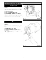

WARNING: BEFORE REMOVING SERVICE ACCESS
COVERS OR THE OIL BURNER ENSURE THAT ALL
ELECTRICAL SUPPLIES TO THE APPLIANCE HAVE
BEEN ISOLATED.
The burners can be removed without disconnecting the oil
supply pipe. However if the filters are being cleaned or a
pressure gauge fitted to the pump then the oil supply
should be turned OFF and arrangements made to catch
any oil which will leak from the oil pump.
SEE FIG. 1
1.
Open up the bottom burner access door. Remove door
and put in a safe place.
(Rayburn 660/680/699K
only)
.
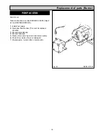
2.
Remove 4 inner panel securing screws and remove
panel.
3.
Remove the 3 plinth securing screws and remove
plinth.
6
PREPARATION
BURNER ACCESS
Burner Removal
Fig. 1
DESN 516793
Summary of Contents for 660
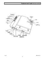
Page 21: ...21 Fig 27 DESN 514774 Replacement of parts Electrical controls ...
Page 22: ...22 Fault Finding Fig 28 Rayburn 600 700 Wiring Diagram 111MB for Individual Satronic boxes ...
Page 23: ...23 Fault Finding Fig 29 Rayburn 600 700 Wiring Diagram 111MB self contained control ...
Page 29: ...Fault Finding 29 Fig 31A DESN 516838 ...
Page 30: ...30 Fault Finding ...
Page 31: ...31 Fault Finding ...
Page 33: ...33 ...
Page 34: ...34 ...
Page 35: ...35 ...