


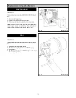
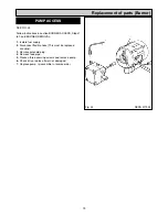


SEE FIG. 20
Follow instructions in sections BURNER ACCESS, Steps
1 to 3, and BURNER REMOVAL.
1. Remove both HT leads from ignitor.
2. Remove mains plug from ignitor.
3. Remove earth screw.
4. Remove 2 ignitor securing screws.
5. Remove ignitor.
6. Fit new ignitor, re-assemble in reverse order.
NOTE:
Boiler burner must be removed from appliance in
order to gain access to ignitor. See instruction in section
burner removal, boiler burner, steps 1 to 4.
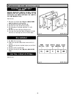
SEE FIG. 21
Follow instructions in sections BURNER ACCESS, Steps
1 to 3, and BURNER REMOVAL.
1.
Remove plug.
2.
Remove solenoid securing nut and washer.
3.
Remove solenoid coil.
4.
Fit new solenoid coil, re-assemble in reverse order.
NOTE:
Boiler burner must be removed from appliance in
order to gain access to solenoid coil. See instruction in
section burner removal, boiler burner, steps 1 to 4.
17
Replacement of parts (Burner)
Fig. 20
DESN 515770
Fig. 21
DESN 515771
SOLENOID COIL
IGNITOR
EARTH
SCREW
Summary of Contents for 660
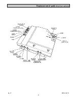
Page 21: ...21 Fig 27 DESN 514774 Replacement of parts Electrical controls ...
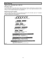
Page 22: ...22 Fault Finding Fig 28 Rayburn 600 700 Wiring Diagram 111MB for Individual Satronic boxes ...
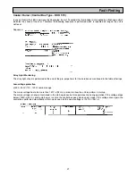
Page 23: ...23 Fault Finding Fig 29 Rayburn 600 700 Wiring Diagram 111MB self contained control ...
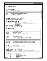
Page 29: ...Fault Finding 29 Fig 31A DESN 516838 ...
Page 30: ...30 Fault Finding ...
Page 31: ...31 Fault Finding ...
Page 33: ...33 ...
Page 34: ...34 ...
Page 35: ...35 ...