


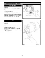


SEE FIG. 17 & 17A
After 15 minutes of the boiler burner running.
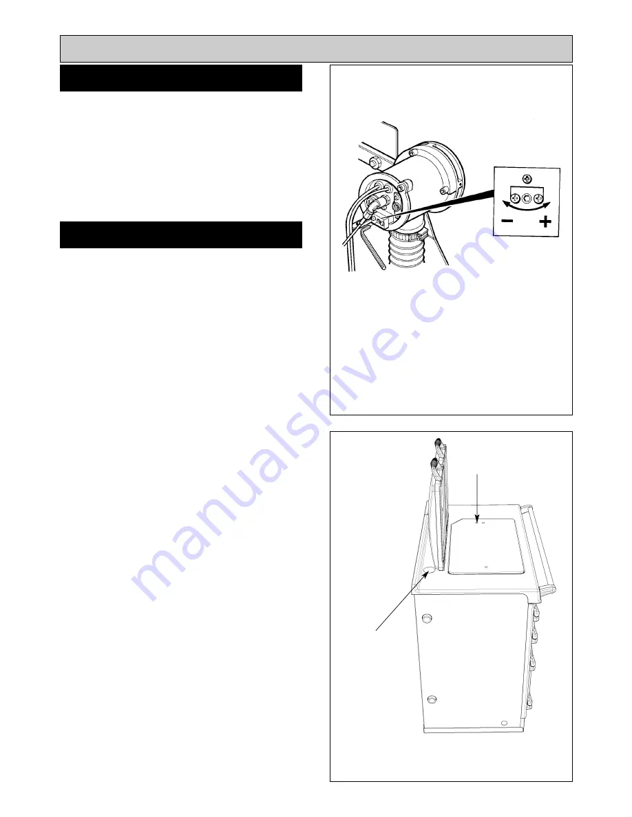
Remove the plug located behind the LH dome lid.
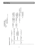
Remove the plugging screw and insert the sensing end of
a portable indicator to check the CO
2
(Carbon Dioxide)
level. Adjust the boiler burner air intake until a reading of
11.0/11.5% is recorded on the indicator.
SEE FIG. 17A
Remove the CO
2
sampling tube and using the same hole
for flue sampling, insert the sensing end of a Baccarach
Smoke Pump and check that the smoke in the boiler
flueways does not exceed No.2 on the scale.
Replace the plugging screw and plug.
Switch off the boiler burner.
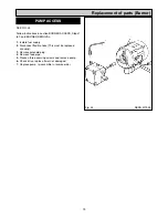
COOKER BURNER - SEE FIG. 17A
Switch on cooker burner.
After 15 minutes of the cooker burner running.
Repeat the above procedures for the cooker burner. To
sample the flue gases from the cooker burner lift up the
RH insulating cover and remove the countersunk headed
screw in the hotplate. The cooker burner should be set to
11.0/11.5% maximum Smoke No.2.
Replace the countersunk headed screw on completion
ensuring that it will not interfere with any pots and pans
placed on the hotplate.
15
SET COMBUSTION AIR
CHECK SMOKE
Re-commissioning
Fig. 17A
Fig. 17
DESN 515637
DESN 512001
COOKER FLUE
SAMPLING HOLE
BOILER FLUE
SAMPLING HOLE
Summary of Contents for 660
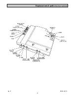
Page 21: ...21 Fig 27 DESN 514774 Replacement of parts Electrical controls ...
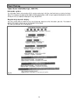
Page 22: ...22 Fault Finding Fig 28 Rayburn 600 700 Wiring Diagram 111MB for Individual Satronic boxes ...
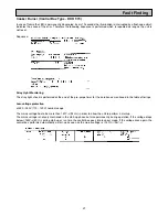
Page 23: ...23 Fault Finding Fig 29 Rayburn 600 700 Wiring Diagram 111MB self contained control ...
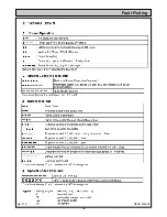
Page 29: ...Fault Finding 29 Fig 31A DESN 516838 ...
Page 30: ...30 Fault Finding ...
Page 31: ...31 Fault Finding ...
Page 33: ...33 ...
Page 34: ...34 ...
Page 35: ...35 ...