


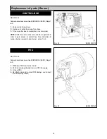
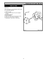


SEE FIG. 8, 8A, 9A, 9B & 9C
It is recommended that each side of the burner is serviced
individually so as not to get the components from the two
burners mixed up.
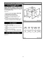
The correct combination of burner blast tubes are shown.
To remove blast tube, slacken two grub screws, pull
forward.
COOKER = Grub screws in head
BOILER = Countersunk screws in tube
680K/780K
660K/760K
10
INTRODUCTION
Burner Servicing
Fig. 8
Fig. 9A
Fig. 9B
DESN 515765
BOILER 8 VANES
COOKER 10
VANES
COOKER 10
VANES
BOILER 10 VANES
3mm HOLES
SMALL SLOTS
Fig. 8A
COOKER BURNER
BOILER BURNER
699K/799K
Fig. 9C
COOKER 10
VANES
BOILER 10 VANES
5mm HOLES
20 LARGE SLOTS
Summary of Contents for 660
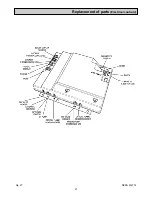
Page 21: ...21 Fig 27 DESN 514774 Replacement of parts Electrical controls ...
Page 22: ...22 Fault Finding Fig 28 Rayburn 600 700 Wiring Diagram 111MB for Individual Satronic boxes ...
Page 23: ...23 Fault Finding Fig 29 Rayburn 600 700 Wiring Diagram 111MB self contained control ...
Page 29: ...Fault Finding 29 Fig 31A DESN 516838 ...
Page 30: ...30 Fault Finding ...
Page 31: ...31 Fault Finding ...
Page 33: ...33 ...
Page 34: ...34 ...
Page 35: ...35 ...