Combined Ventilation Controller
RVS-22HA
4-stage Control for Power Applications
2 variable speed stages
and 2 thermo/mister cycle stages
Installation Guide
Read this guide carefully before installing the controller.
Page 1: ...ed Ventilation Controller RVS 22HA 4 stage Control for Power Applications 2 variable speed stages and 2 thermo mister cycle stages Installation Guide Read this guide carefully before installing the controller ...
Page 2: ...evice on the supply circuit as well as an external relay on all ON OFF stages to prolong the life of the controller We strongly recommend connecting the controller to an alarm system and installing a supplementary natural ventilation system as well as a back up thermostat on at least one cooling stage Refer to the wiring diagram enclosed with this installation guide to connect the thermostat PRECA...
Page 3: ...cting a Motor Type for Stage 1 8 Selecting a Motor Type for Stage 2 8 TEMPERATURE UNITS 8 TEMPERATURE PROBES 9 Connecting the Probes 9 Extending the Probes 9 Installing the Room Probes 9 Installing the Humidity Probe 9 Defective Probes 9 TROUBLESHOOTING GUIDE 11 TECHNICAL SPECIFICATIONS 13 FACTORY SETTINGS 14 WIRING DIAGRAM 16 RA Y DOT Ventilation Control Page 1 ...
Page 4: ...ications The User s Guide explains the workings of the controller parameters RVS 22HA highlights Displays absolute temperatures for all stages Temperature readings and high low for both room and individual readings Selectable 2 F offset for all on off stages Optional humidity probe reading and high low with relative humidity compensation Alarms for high low and critical temperatures power failure ...
Page 5: ...a change in voltage will depend on the make and capacity of the motor In order to achieve a high degree of compatibility between controller and motor the user can choose from ten different motor types thus ensuring that the correct voltages are supplied Humidity compensation The stage 1 minimum speed can be adjusted automatically as a function of relative humidity As humidity increases the minimum...
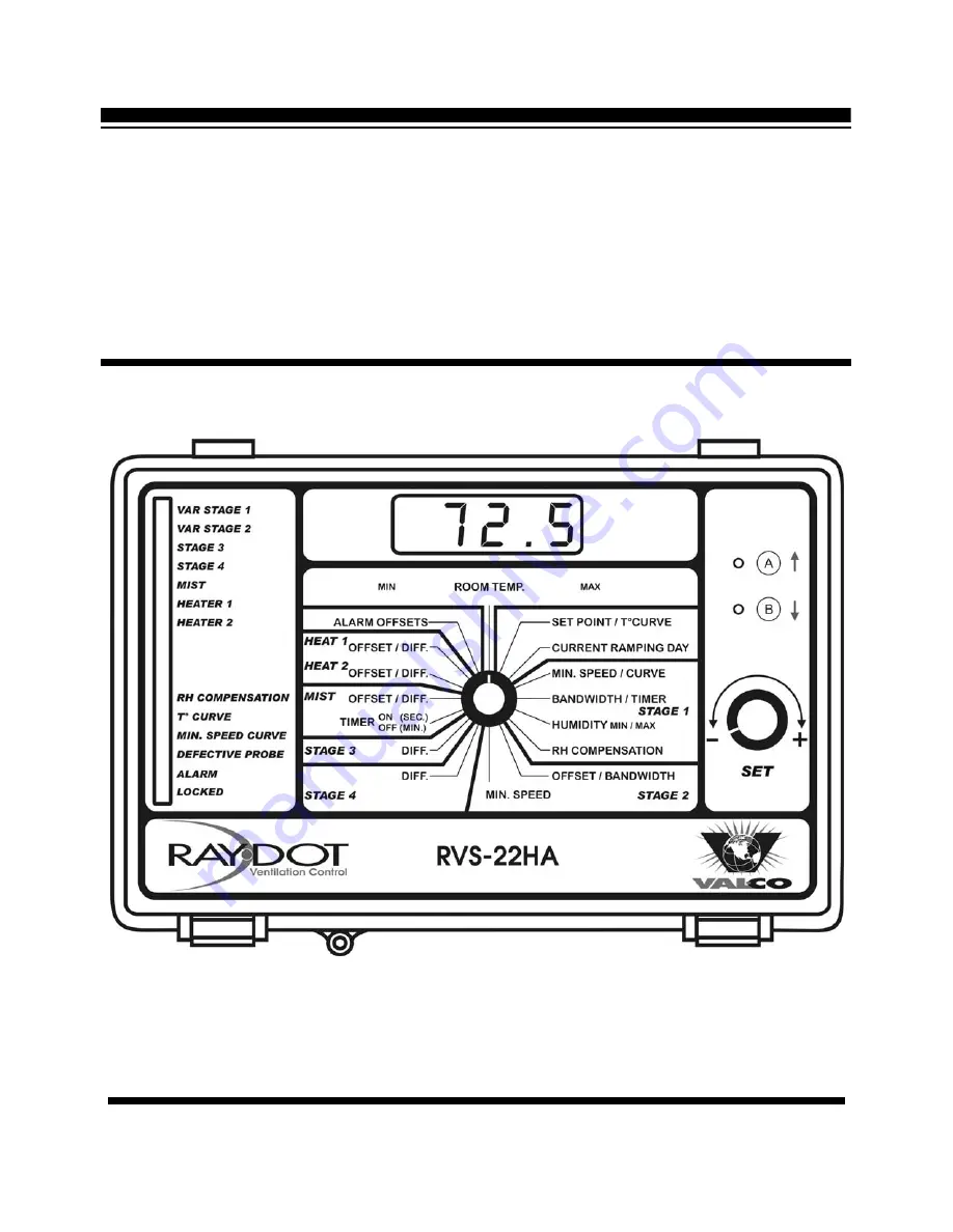
Page 6: ...CONTROL INTERFACE COVER 1 2 3 4 5 13 pilot lights Page 4 RA Y DOT Ventilation Control ...
Page 7: ... Variable stage 2 Lights up when the fan variable stage 2 is activated Stage 3 Lights up when stage 3 is activated Stage 4 Lights up when stage 4 is activated Mist Turns on when the mister cycle stage is activated Heater 1 Lights up when heater 1 is activated Heater 2 Lights up when heater 2 is activated RH compensation Turns on when relative humidity is being compensated Temperature curve Is on w...
Page 8: ...ameters Temperature units 2 ON OFF Celsius Fahrenheit Probe 2 3 ON OFF Enabled Disabled Probe 3 4 ON OFF Enabled Disabled Probe 4 5 ON OFF Enabled Disabled Cooling or heating 6 and 7 6 OFF 6 ON 6 ON and 7 ON or OFF and 7 ON and 7 OFF Stage 3 Fan Stage 3 Heater Stage 3 Fan Stage 4 Fan Stage 4 Heater Stage 4 Heater Temperature heater 8 ON OFF Zoned Heaters Cascading Heaters Mist 9 ON OFF Enabled Dis...
Page 9: ... wiring diagram enclosed with this installation manual 1 Set the voltage switch to the appropriate line voltage 2 Drill access holes on the bottom of the enclosure only Do not drill holes on the side or the top of the enclosure 3 It may be necessary to install a transformer on the heating stage in order to supply the appropriate voltage to the heating unit Alarm Connection There are two types of a...
Page 10: ...e make and capacity of your stage 1 variable speed motors and note the corresponding type number 1 to 10 1 Set the parameter selection knob to BANDWIDTH TIMER STAGE 1 The stage 1 bandwidth appears flashing on the display 2 Press the push button u The message tyP appears on the display alternating with the currently selected type number which flashes 3 Using the adjustment knob adjust the type numb...
Page 11: ...0 meters To extend a probe 1 Use a shielded cable of an outside diameter ranging between 0 245 and 0 260 in 6 22 and 6 60 mm to ensure the cable entry is liquid tight Cable size should not be under 18 AWG 2 It is preferable to solder the cable joints to ensure a proper contact between the two cables and to solder the shields Installing the Room Probes Locate the room probe connected to terminal 1 ...
Page 12: ...n displays Pr alternating with the temperature measured by the corresponding probe Otherwise the letter displays Pr alternating with Pr Lo or Pr Hi Humidity Probe If the humidity probe is defective or if there is no humidity probe the defective probe pilot light does not turn on but the display shows the letter P Lo or P Hi when the parameter selection knob is set to STAGE 1 HUMIDITY refer to Stag...
Page 13: ...esistance is induced on a probe Be sure the probes are dry Locate them away from drafts and sources of radiant heating The display shows sudden variations in the room temperature There is electrical noise near a probe cable Isolate the probe cables from all high voltage sources Do not route probe cables and other power cables through the same electrical knockout Do not run probe cables next to oth...
Page 14: ...s continuously when the room temperature is below the room set point or when the controller operates in minimum ventilation cycle Humidity compensation is activated and relative humidity exceeds the humidity set point Adjust the humidity set point or deactivate compensation as required The wiring is incorrect Be sure that two wires connect each stage to the corresponding terminal The fan motor hea...
Page 15: ...mal charge 25 mA 50 60 Hz Alarm relay 1 A 30 VDC Stage 1 and stage 2 power source line 1 and line 2 115 230 VAC 20 10 50 60 Hz same as line power Stage 1 and stage 2 fuse 15 A 250 VAC slow blow Storage temperature 4 F to 130 F 20 C to 55 C Operating temperature 32 F to 120 F 0 C to 50 C Temperature range inside probes 6 F to 168 F 21 C to 76 C Weight 5 2 lbs 2 36 kg Dimensions 11 X 7 X 6 27 9 X 17...
Page 16: ...nsation Option OFF ON OFF Humidity Set Point 65 10 to 90 RH STAGE 1 R H COMPENSATION R H Speed Compensation 50 0 to 100 The Test Mode simulates a temperature reading allowing the user to test the control s reaction at a given temperature To access the Test Mode the user must position the parameter selection knob to ROOM TEMP and press push button A or B until tESt appears alternating with OFF on t...
Page 17: ... 1 0 to 20 minutes Offset 8 0 F 7 0 C Differential 2 0 F 1 0 C 0 5 to 20 0 F 0 3 to 11 0 C MIST OFFSET DIFF Humidity Turn Off 75 40 to 90 RH OFF Offset 3 0 F 3 0 C 10 0 to 20 0 F 5 5 to 11 0 C Differential 2 0 F 1 0 C 0 5 to 20 0 F 0 3 to 20 0 C HEAT 2 OFFSET DIFF Max Diff Prot Bet Zones 7 5 F 4 2 C 5 0 to 40 0 F 0 3 to 20 0 C OFF Offset 3 0 F 3 0 C 10 0 to 20 0 F 5 5 to 11 0 C HEAT 1 OFFSET DIFF ...
Page 18: ...WIRING DIAGRAM Page 16 RA Y DOT Ventilation Control ...
Page 19: ......
Page 20: ...MAY22 v1 1 ...