4
Navigation Overview:
15
NAVIGATION OVERVIEW
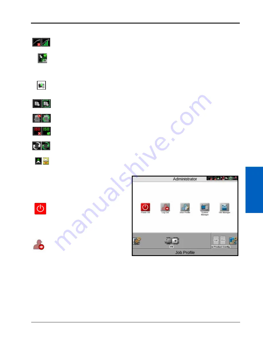
The following status indicators will be displayed in the status header:
ADMINISTRATOR OR USER PANEL
Touch Administrator or User Name at the top of the
display to access the Administrator or User Panel and
the following utilities:
POWER DOWN
Touch the power down icon to shut down the ROS
device. It is recommended to shut down the device
using this icon prior to removing power from the ROS
device by switching the vehicle ignition off.
LOG OUT
Touch the log out icon to exit the current user profile.
Log out of the ROS device when leaving the equipment for short periods or at the end of the shift or when
switching operators to secure the management system from unauthorized access or operation of the control
system.
NOTE:
Demonstration mode features are also available via the logout prompt.
Review Chapter 5, Administrator and User Profiles, for additional assistance with user profiles and security features
available with ROS.
Slingshot
®
.
The status of a Slingshot Field Hub is displayed. A red X will display on this indicator if a
Field Hub is not connected or not detected. When a Field Hub is connected to the ROS device,
this area will display the current signal strength for wireless communication status.
GPS.
This indicator displays the current status of the position solution. This indicator will display:
•
Green if the status of GPS is okay
•
Yellow if an error or cautionary condition has been encountered
•
Red if GPS is non-functional
Software Update Available.
One of these status displays will be available if a ROS update or feature
unlock file is available. The update will remain available even after the USB flash drive is
disconnected from the device to allow the operator to perform the update process at a
convenient time during the day and without disrupting field operations.
File Transfer.
the status header displays the status of wireless file transfers with a Slingshot
®
Field
Hub. If a file transfer is in progress, the file transfer indicator will display a green “in progress”
status.
CANbus Communications.
This indicator displays the communication status for a CANbus system. A
green indicator will be displayed when communication is detected without errors.
ISOBUS Communications.
This status display indicates the status of ISObus communication with
ECUs, working sets, implements, etc. This status will only be shown if an ISObus ECU is detected by
the ROS device.
Serial Communications.
This indicator displays the communication status for serial communication
ports. A green indicator will be displayed when all configured communication ports.
Forward/Reverse.
The forward/reverse status indicator shows if the machine is traveling forward or
reverse according to the ROS device.
Summary of Contents for viper
Page 16: ...CHAPTER 2 8 Viper Viper 4 Installation Operation Manual ...
Page 48: ...CHAPTER 6 40 Viper Viper 4 Installation Operation Manual ...
Page 67: ...File Manager 59 FILE MANAGER ...
Page 68: ...CHAPTER 7 60 Viper Viper 4 Installation Operation Manual ...
Page 112: ...CHAPTER 9 104 Viper Viper 4 Installation Operation Manual ...
Page 174: ...CHAPTER 16 166 Viper Viper 4 Installation Operation Manual ...
Page 176: ...CHAPTER 17 168 Viper Viper 4 Installation Operation Manual ...


