Instructions for Use MPR1 DATALOGGER
Manufacturer:
RAUMEDIC AG, Hermann-Staudinger-Strasse 2, 95233 Helmbrechts, Germany
Page 41 of 98
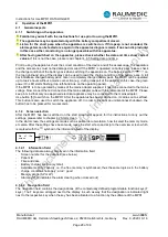
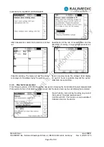
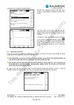
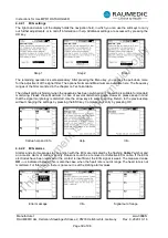
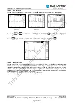
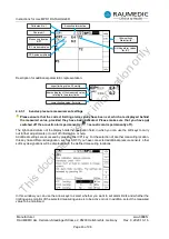
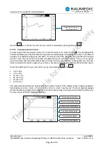
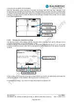
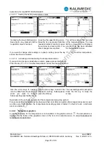
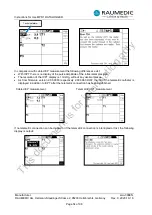
Elongation of the time axis with the following graduation of the time range displayed:
•
3 min. 50 s
•
7 min. 40 s
•
19 min. 10 s
•
38 min. 20 s
•
76 min. 40 s
•
3 h 50 min.
The somewhat odd values are produced by the number of pixels of the display range; roughly speaking a
trend display of 4 min., 8 min., 20 min., 40 min., 80 min., and 4 h can be set.
Finer temporal resolution
Coarser temporal resolution
Rough backward navigation
Fine backward navigation
Fine forward navigation
Rough forward navigation
4.4.3 Transducer for invasive pressure measurement
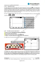
Observe chapter 3.2 Cabled invasive pressure measurement
Use approved accessories only.
Observe the instructions for use of the accessories.
Observe the permissible measuring range of the transducer.
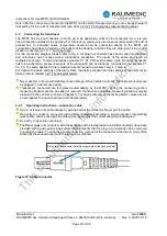
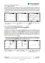
The MPR1 has three pressure input sockets P1, P2, P3, to connect pressure sensors (external transducers
or micro-chip precision pressure catheters). It is insignificant for the further measurement, to which of the
three input sockets the pressure sensor is connected. The pressure sensor connected is recognised
automatically. The same applies corresponding, if you want to connect further pressure sensors.
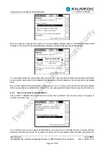
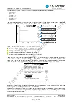
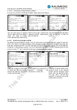
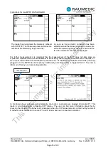
You have already opened a new patient document and the memory mode has been set. The MPR1
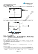
recognises that you have connected a pressure sensor to socket P1. In this screen you can select the
measuring location and the process for the zero calibration.
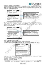
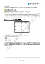
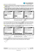
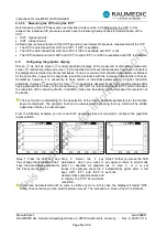
If you want to begin with the selection of the measuring location, press the Menu key. The pull-down menu
with the overview of the measuring locations available will open. Please keep in mind that you can allocate
a measuring location once only.
This
document
is
for
information
only

