background image


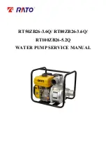
RT50ZB26-3.6Q/ RT80ZB26-3.6Q/ 

RT100ZB26-5.2Q 

WATER PUMP SERVICE MANUAL 


Summary of Contents for RT50ZB26-3.6Q

Page 1: ...RT50ZB26 3 6Q RT80ZB26 3 6Q RT100ZB26 5 2Q WATER PUMP SERVICE MANUAL...

Page 2: ...O Company s written permission SAFETY MESSAGES Your safety and the safety of others are very important We have provided important safety messages in this manual and on the generator Please read these...

Page 3: ...ERVICING 16 4 1 Troubleshooting 16 4 1 1 Starting Difficult 16 4 1 2 Power lack 19 4 1 3 Speed unstable 20 4 1 4 WATER PUMP UNABLE DISCHARGE 20 4 1 5 Exhaust gas color abnormal 21 4 1 6 Unable ignitin...

Page 4: ...1 Component identification CHOKE LEVER FUEL COCK ENGINE SWITCH DISCHARGE PORT FUEL TANK CAP OIL DIPSTICK RECOIL STARTER GRIP PUMP DRAIN PLUG SUCTION PORT PRIMING WATER FILTER CAP OIL DRAIN PLUG MUFFE...

Page 5: ...splacement 196cm3 270cm3 Compression Ratio 8 5 1 8 2 1 Bore Stroke 68 54mm 77 58mm Maximum output Power 4 0kW 3 600rpm 5 8kW 3 600rpm Maximum Torque 11N m 2 500rpm 17N m 2 500rpm Cooling System Forced...

Page 6: ...mm 2 in 80 mm 3 in 100 mm 4 in Discharge port diameter 50 mm 2 in 80 mm 3 in 100 mm 4 in Suction head maximum m 8 8 8 Total head maximum m 25 26 30 Discharge capacity maximum m3 h 36 60 96 Specified...

Page 7: ...2 DIMENSION AND TORQUE 4 2 DIMENSION AND TORQUE 2 1 Engine dimension R200...

Page 8: ...2 DIMENSION AND TORQUE 5 R270...

Page 9: ...2 DIMENSION AND TORQUE 6 PTO dimension figure Item Figure 13301 Z040310 13301 Z080310...

Page 10: ...2 DIMENSION AND TORQUE 7 2 2 Water pump dimension RT50ZB26 3 6Q...

Page 11: ...2 DIMENSION AND TORQUE 8 RT80ZB26 3 6Q...

Page 12: ...2 DIMENSION AND TORQUE 9 RT100ZB26 5 2Q...

Page 13: ...M10 1 25 10 1 0 Crankcase cover bolt M10 1 25 2 0 2 Muffler assembling nut M8 1 25 24 2 4 Air cleaner assembling nut M6 1 0 9 0 9 Oil drain bolt M10 1 25 18 1 8 Fuel tank assembling bolt nut M6 1 0 10...

Page 14: ...cifications Torque valve N m kg m Frame M8 1 25 24 2 2 4 2 Pump body M10 1 25 26 2 2 6 2 Connecting tray M8 1 25 20 2 2 0 2 Impeller M8 1 25 20 2 2 0 2 Suction port M8 1 25 10 2 1 0 2 Discharge port M...

Page 15: ...heck Air cleaner element Clean Fuel strainer Clean Spark plug Clean Adjust Valve gap Check Adjust Fuel tank fuel element Clean Check Fuel tube Replace Every 2 years Every 4 years Clean the air cleaner...

Page 16: ...ve the nut air cleaner cover and wing nut Remove polyurethane and paper elements 2 Clean polyurethane with detergent then blow it dry with compressed air or squeeze it dry Dip the element in clean oil...

Page 17: ...with a stiff wire brush Check gasket for damaged 2 Measure plug gap between center electrode and side electrode with spark plug feeler If necessary adjust the gap by bending the side electrode Spark...

Page 18: ...anner then tighten the locknut d Recheck valve clearance after tightening the rocker arm lock nut 3 7 Governor 1 Remove the fuel tank 2 Loosen the nut on the governor arm Check the throttle for fully...

Page 19: ...to get through Float is damaged or sticking Repair float Fuel supply is normal Fuel is too filthy or deteriorated Replace There is water in fuel Replace Too much fuel in engine Drain extra fuel dry u...

Page 20: ...g never hold the high tension line of the spark plug with wet hand Make sure there is no spilled fuel outside the engine and that the spark plug isn t dipped with fuel To prevent fire keep sparks far...

Page 21: ...4 DISASSEMBLING AND SERVICING 18 3 Motor running abnormal Motor relay failure wiring loosen off and starting switch failure Check and remove the starting electric appliance or replace damaged parts...

Page 22: ...g chamber Clear away Air cleaner is clogged up Clean air cleaner filter element Intake pipe is leaking Repair or replace Poor compression Intake pipe is leaking Repair or replace Piston or cylinder or...

Page 23: ...float chamber Clean improper spark plug electrodes clearance Adjust Something wrong with induced coil and so on Check and replace damaged parts 4 1 4 WATER PUMP UNABLE DISCHARGE NO WATER DISCHARGINE C...

Page 24: ...element 4 1 6 Unable igniting TROUBLE CAUSE REMEDY Unable igniting Fuel supply System Fuel is finished Refill fuel Carburetor is clogged Check fuel line and dredge Float is leaking Repair Needle valve...

Page 25: ...w and green lead is normal 4 1 8 GASOLINE ENGINE IS OVERERHEAT TROUBLE CAUSE REMEDY Gasoline engine is overheat Oil insufficient or wrong oil ratio in the gasoline Refill engine oil Exhaust pipe block...

Page 26: ...rator should be familiar with the working principle and structure of the gasoline engine knowing how to make an emergent stop and the operation of all controlling parts Anyone without training is forb...

Page 27: ...company will not assume any responsibility for person hurt or equipment damaged caused by disregarding this warning label Label is shown as following 1 Fuel label 88002 V010210 2 Reading Owner s Manu...

Page 28: ...SSEMBLING AND SERVICING 25 5 Warning label 88006 V010710 6 Warning label 88006 V010810 7 Warning label 88006 V010610 8 Crankshaft direction indicator label 88036 V010110 9 Throttle valve label 88028 Z...

Page 29: ...4 DISASSEMBLING AND SERVICING 26 10 Air cleaner maintenance label 88005 Z010110 11 Impeller direction indicator label 88035 V010110 12 Oil brand label 88031 Z010110 13 Filling oil label 88027 V010110...

Page 30: ...4 DISASSEMBLING AND SERVICING 27 14 Specification label 88016 V010210 88016 V020210 88016 V030210...

Page 31: ...6 Diamond lap 450 7 Diamond lap 320 8 Flywheel driver 9 Bearing extractor 10 Valve guide reamer Carburetor float level inspection Valve guide removal installation Assembling ball bearing Installing h...

Page 32: ...ERVICING 29 4 3 Dismounting chart Connecting tray Shock absorption Suction port Impeller Discharge port Pump body Frame Fuel tank Muffler Gasoline engine Air cleaner Carburetor Recoil starter Shroud F...

Page 33: ...y reassembly Disassemble and reassemble in the impacting starter assembling state Black white lead Connect to starter lead Yellow lead Connecting to oil level switch lead Fan cover Impack starter Engi...

Page 34: ...tarter rope through the rope in the recoil starter pulley and make a figure eight knot at the rope end Hang the side hook of the recoil starter spring in the groove of the recoil starter case set the...

Page 35: ...pulley and install the return spring on the recoil starter pulley while hooking it on the side of the driving cam Install the spring driving guide and fixing screw in order Pass the recoil starter rop...

Page 36: ...n coil and flywheel with the feeler c Adjust the clearance of the ignition and flywheel d Adjusting method Loosen the bolt and move the ignition coil up and down for adjusting the clearance then screw...

Page 37: ...of the coil with the spark plug cap removed touching one test lead to the high tension cord while touching the other tester lead to the coil s iron core Secondary side resistance value 5 7k recommend...

Page 38: ...LEMENT POLYURETHANE SILENT NOSE ONLY FOR SILENCE ELBOW packing AIR CLEANER ELBOW Disassembly reassembly remove and install with the choke lever and fuel valve in the ON position Clean the inside of th...

Page 39: ...R GRID ELBOW PACKING COLLAR AIR CLEANER CASE Oil capacity 60cc reassembly after cleaning with solvent fill with clean oil and install AIR CLEANER ELBOW Disassembly reassembly Remove and install with t...

Page 40: ...throttle return spring Pull the carburetor forward to a point where the groove in the throttle arm lines up with the rod And lift the rod out of its hole Reassembly Blow out the passages with compres...

Page 41: ...FUEL DRAIN BOLT SET BOLT After assembly check for any sign of fuel leakage Reassembly Clean thoroughly with compressed air before installation reassembly Inspect for wear before installation Adjustme...

Page 42: ...he carburetor in the position as shown and push the float in by finger and measure the distance between the float and case at the float valve bottom float height Specified float height 13 7mm If the f...

Page 43: ...TUBE GUIDE SEAL EX GUIDE TUBE GASKET CYLINDER HEAD COVER ADJUSTING BOLT CYLINDER HEAD Installation Before installation remove any carbon deposits from the combustion chamber and inspect the valve sea...

Page 44: ...the standard or service limit or if visually inspecting the burn and damaged on the valve face please replace with new one Valve spring free length Measure the free length of the valve Springs If out...

Page 45: ...lve guide out of the combustion chamber side using valve guide driver NOTICE Be careful to avoid damaging the cylinder head when driving out the valve guides c Install the new valve guides from the va...

Page 46: ...peration If the valve does not operate smoothly the guide may have been bent during installation Replace the valve guide if it is bent or damaged e Check the valve stem to guide clearance f The valve...

Page 47: ...urn the cutter as you lift it from the valve seat Tool Valve seat cutter Use the 32 45 cutters to narrow and adjust the valve seat so that it contacts the middle of the valve face The 32 cutter remove...

Page 48: ...14 4 Don t reuse Apply oil to lip of the oil seal WASHER 8 4 19 5 0 8 Install inside the seat BALANCING SHAFT BEARING 6207 OILSEAL 35 52 7 PISTON PISTON PIN PISTON PIN CLIP OIL SENSOR BOLT M6 16 CAMSH...

Page 49: ...f the oil seal when reassembling crankcase cover PIN Fix the governor arm with pin after installing SPACER 6 2 15 0 6 OIL seal 25 41 25 6 CONNECTION ROD PISTON PIN PISTON PIN CLIP PISTON CRANKCASE CRA...

Page 50: ...top ring and the second ring top ring with chrome plated After assembly check for smooth movement of the piston ring Stagger the piston ring end gaps 120 apart Reassembly a Piston pin clip Install by...

Page 51: ...n with meter scraper or metal brush a Piston skirt O D Measure the piston skirt O D with outside micrometer if out of the service limit replace it Standard Service limit 67 985mm R200 67 845 mm R200 7...

Page 52: ...n ring should be freely turned without loosening and sticking Then measure with inserting feeler into clearance of the ring and upper and lower face Standard Service limit 0 015 0 045mm 0 15mm e Pisto...

Page 53: ...cting rod Standard Service limit 18 002mm R200 18 07mm R200 18 002mm R270 18 07 mm R270 b Check big end diameter If out of the standard or exceed service limit replace the connecting rod Standard Serv...

Page 54: ...ith cam and journal which can control intake and exhaust When operating camshaft operating face and lifter will be badly rubbed from periodically impacting and easily be damaged So the camshaft shall...

Page 55: ...seriously worn in the high speed rubbing stat Second installing precision problem when the matching clearance of the camshaft journal and camshaft seat or bearing is out of the service limit camshaft...

Page 56: ...ARGE PORT FILTER CAP Gasket IMPELLER Don t dismount it from the water connecting tray as can as possible MECHANICAL SEAL VOLUTE CASE After installing check the gap between impeller and the volute case...

Page 57: ...the connecting tray as shown on the right figure Measure d e f three points take average value of three points 4 Volute depth A impeller height B impeller clearance Specified impeller clearance 0 8 1...

Page 58: ...Q RT80ZB26 3 6Q Install the engine case on the installing seat by aligning with four holes of the bottom face ENGINE INSTALLING SEAT FRAME COMP SHOCK ABSORPTION SEAT Check for cracked or worn before i...

Page 59: ...Install the engine case on the installing seat by aligning with four holes of the bottom face ENGINE INSTALLING SEAT WATER PUMP INSTALLING SEAT SHOCK ABSORPTION SEAT Check for cracked or worn before...

Page 60: ...POWER CO LTD Factory address China NO 99 Jiujiang Road Shuangfu District Chongqing Tel 86 23 85553441 Fax 86 23 85553450 Postcode 402247 Http www rato cc E mail ratoservice rato cc parts rato cc 9300...

Reviews: