background image

AS316 / AS316S User Guide

POWER SUPPLY MODULES

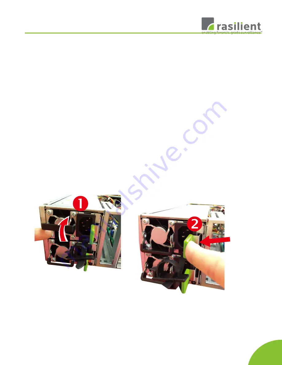
Removing a PSU module

Remove power cables connected to the PSU module. 

Allow a minute for fan to spin down. 

Pushing the latch then hold the tray handle tab. 

Then pull the PSU module gently until it slides out of the 
enclosure. 

Installing a PSU Module

Slide in PSU module. 

Make sure the latch on the module is fully hooked onto 
the PSU housing.


32                        

Summary of Contents for AS316

Page 1: ...ent contains confidential information that is proprietary to Rasilient or confidential information which Rasilient has legal duty to protect from disclosure The information contained in this document may not be disclosed without the express written permission of Rasilient Systems Inc ...

Page 2: ...f the product herein Nothing herein may be construed as granting any right or license relating to any intellectual property rights of this manual or product Unless otherwise provided in the Purchase and Sale Agreement for this product manufacturer and distributor of this product will not be liable whatsoever relating to the distribution and or use of this product In addition manufacturer and distr...

Page 3: ...pliance 12 Product EMC Compliance 12 Communications Commission Notice 13 Class A Equipment 13 Declaration of Conformity for Products Marked with the FCC Logo United States Only 13 European Union Notice 14 Canadian Notice Avis Canadien 14 Power Cords 14 Chapter 1 Introduction 16 AUDIENCE ASSUMPTIONS 17 ABOUT THIS GUIDE 17 PACKING CHECKLIST 17 SPECIFICATIONS 18 PRODUCT FEATURES 19 SYSTEM OVERVIEW 19...

Page 4: ... AS316S User Guide Removing a Hard Disk Drive 29 Remove HDD out from HDD tray 30 POWER SUPPLY MODULES 32 Installing a PSU Module 32 MOUNTING THE SYSTEM ONTO A RACK 33 Installing the tool less rack rail 33 3 ...

Page 5: ...AS316 AS316S User Guide List of Figures Figure 1 AS316 AS316S Front View 19 Figure 2 Rear View of AS316 21 Figure 3 AS316 Rear I O Ports 22 Figure 4 AS316S Rear I O 23 4 ...

Page 6: ...AS316 AS316S User Guide List of Tables Table 1 Safety Compliance 12 Table 2 European Union Compliance 14 Table 3 Drive Slot Mapping 20 5 ...

Page 7: ...AS316 AS316S User Guide About this Manual Conventions Safety Symbols Safety Precautions Regulatory and Integration Information 6 ...

Page 8: ...ng symbols used throughout this manual Warning Provides information to prevent injury in the process of completing a task Caution Provides information to prevent damage to the components in the process of completing a task Important Provides information required for completing a task Note Provides tips to aid in completing a task 7 ...

Page 9: ...ce Only Any receptacle e g RJ45 marked with this symbol indicates a network interface connection To reduce the risk of electric shock fire or damage to equipment do not plug telephone ortelecommunications connectors into this receptacle WARNING This symbol on power supplies or systems that the equipment is supplied by multiple sources of power To reduce the risk of injury from electric shock remov...

Page 10: ...ed the level of repairs specified in these procedures The system is designed to be electrically grounded To ensure proper operation plug the AC power cord into a properly grounded AC outlet only Electrostatic Discharge Precautions Electrostatic discharge ESD can damage static sensitive devices or micro circuitry Proper packaging and grounding techniques are required to prevent damage Keep electros...

Page 11: ...duce the risk of personal injury or damage to equipment always ensure that the rack is adequately stabilized prior to extending a component outside the rack A rack may become unstable if more than one component is extended Extend only one at a time Do not stand or step on any components in the rack If installed in a closed or multi unit rack assembly the operating ambient temperature of the rack e...

Page 12: ... at all times Unplug the power cord from the power supply module to shut off power to the equipment Protect the storage system from power fluctuations and temporary power interruptions with a regulating uninterruptible power supply UPS This device protects the hardware from damage caused by power surges and voltage spikes and keeps the system operational during a power failure The storage system m...

Page 13: ...e or model number Product Regulatory Compliance Product Safety Compliance This system complies with the following safety requirements Table 1 Safety Compliance EN 62368 1 2014 2nd Edition A11 2017 Safety of Information Technology Equipment IEC 62368 1 2nd Edition Rev February 26 2014 Safety of Information Technology Equipment Worldwide Safety approvals can be supplied upon request Please contact y...

Page 14: ... not have an FCC logo or FCC ID on the label Class B devices have an FCC logo or FCC ID on the label Once the class of the device is determined refer to the following corresponding statement Class A Equipment This equipment has been assembled with components that comply with the limits for a Class A digital device pursuant to Part 15 of the FCC Rules These limits are designed to provide reasonable...

Page 15: ...2013 Power Line Flicker Canadian Notice Avis Canadien Class A Equipment This Class A digital apparatus meets all requirements of the Canadian Interference Causing Equipment Regulations Cet appareil numérique de la classe A respecte toutes les exigences du Règlement sur le matériel brouilleur du Canada Power Cords The power cord set included in the system meets the requirements for use in the count...

Page 16: ...m 6 feet and 3 6m 12 feet If you have questions about the type of power cord to use contact your sales representative The following statement applies only to rack installed products that are GS Marked This equipment is not intended for use at workplaces with visual display units in accordance with 2 of the German ordinance for workplaces with visual display units 15 ...

Page 17: ...AS316 AS316S User Guide Chapter 1 Introduction Audience Assumptions About This Guide Packing Checklist Specifications Product Features System Overview 16 ...

Page 18: ...IP addresses install appropriate VMS software to administer and view the cameras This manual is generally organized as follows PACKING CHECKLIST Make sure you have all the components shipped with your system If any item is damaged or missing please contact your sales representative for replacement The AS316 AS316S is shipped with the following Chassis 3U Enclosure Solid State Disk Drives Two 240 4...

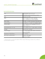
Page 19: ... USB 3 0 2xHDMI mDP Max Storage Up to 288TB Up to 960GB for OS 2x SSD in RAID 1 Dimensions W x D x H 17 x 26 8 x 5 2 430 x 680 x 133 mm Weight Max 09 Lbs 49 Kgs Power Supply 1 1 Redundant 800 1200W 100 240V AC 6A 47 63Hz Operating Temperature 10 35 C Recording Performance1 AS316 500 Mbps AS316S 2Gbps 1 Recording performance was testing using Milestone XProtect VMS and RAID5 storage Performance may...

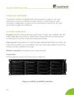
Page 20: ...is built around high performance Intel Xeon Scalable CPU and DDR4 2666 MHz ECC memory AS316 offers high performance and bandwidth connectivity to meet the most demanding requirements Purpose built Open platform to integrate Video Management Software VMS All major VMS providers are pre qualified Most are continually added to ensure the widest possible certification coverage Effortless installation ...

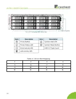
Page 21: ...AS316 AS316S User Guide Table 3 Drive Slot Mapping 1 2 3 4 5 6 7 8 9 10 11 12 13 14 15 16 20 ...

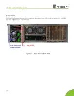
Page 22: ...AS316 AS316S User Guide Rear View Following diagram shows the location of all the rear I O ports on AS316 AS316S Power Supplies are also shown Figure 2 Rear View of AS316 21 ...

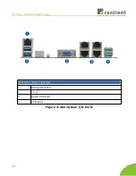
Page 23: ...AS316 AS316S User Guide 22 AS316 Rear Panel Connectors 1 Management Port 2 VGA 3 Quad 1GbE Ports 4 USB Ports Figure 3 AS316 Rear I O Ports ...

Page 24: ...rs 1 PS2 Keyboard and Mouse 2 USB BIOS Flashback Button 3 USB 3 1 Gen 2 Type A Port 4 LAN Ports 5 USB 2 0 Ports 6 USB 3 1 Type C 7 USB 3 1 Gen 1 Ports 3 4 8 USB 3 1 Gen 1 Ports 1 2 9 Optical S PDIF OUT 10 Audio Output Ports Figure 4 AS316S Rear I O 23 ...

Page 25: ...AS316 AS316S User Guide 24 ...

Page 26: ...AS316 AS316S User Guide Chapter 2 Hardware Installation Hard Disk Drives Power Supply Modules Mounting the System onto a Rack 25 ...

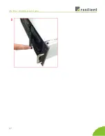
Page 27: ...S User Guide HARDWARE INSTALLATION This chapter provides detailed instructions on hardware installation HARD DISK DRIVES Removing Installing a Drive Tray Pull out the HDD tray handle and slide out the HDD tray 26 ...

Page 28: ...AS316 AS316S User Guide 27 ...

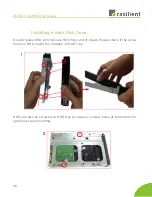
Page 29: ...Disk Drive Directly place HDD into tool less HDD tray until it snaps Please check if the screw holes on HDD match the dimples on HDD tray HDD can also be screwed on HDD tray by reserve 2 screw holes at the bottom for optional screw mounting 28 ...

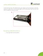
Page 30: ... tray into chassis HDD cage Make sure the drive tray is correctly secured in place when its front edge aligns with the bay edge Push the tray lever until it reaches the end and clicks Removing a Hard Disk Drive Push up HDD from the bottom 29 ...

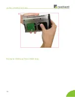
Page 31: ...AS316 AS316S User Guide Remove HDD out from HDD tray 30 ...

Page 32: ...AS316 AS316S User Guide 31 ...

Page 33: ...cted to the PSU module Allow a minute for fan to spin down Pushing the latch then hold the tray handle tab Then pull the PSU module gently until it slides out of the enclosure Installing a PSU Module Slide in PSU module Make sure the latch on the module is fully hooked onto the PSU housing 32 ...

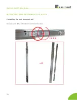
Page 34: ...AS316 AS316S User Guide MOUNTING THE SYSTEM ONTO A RACK Installing the tool less rack rail Release and detach the inner rail from the slide 33 ...

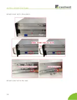
Page 35: ...AS316 AS316S User Guide Attach inner rail to the system Attach outer rail to the rack 34 ...

Page 36: ...AS316 AS316S User Guide 35 ...

Page 37: ...AS316 AS316S User Guide WARNING CAUTION Verify ball bearing retainer is locked forward Pull out the intermediate rail until locked out Slide release tab and push system into rack 36 ...

Reviews: