background image

Connecting to the Device

You can connect the MobileTrace

®

to a laptop or PC simply by connecting the device to your computer’s local

area network (LAN) through a device capable of assigning IP addresses (such as an Ethernet router).

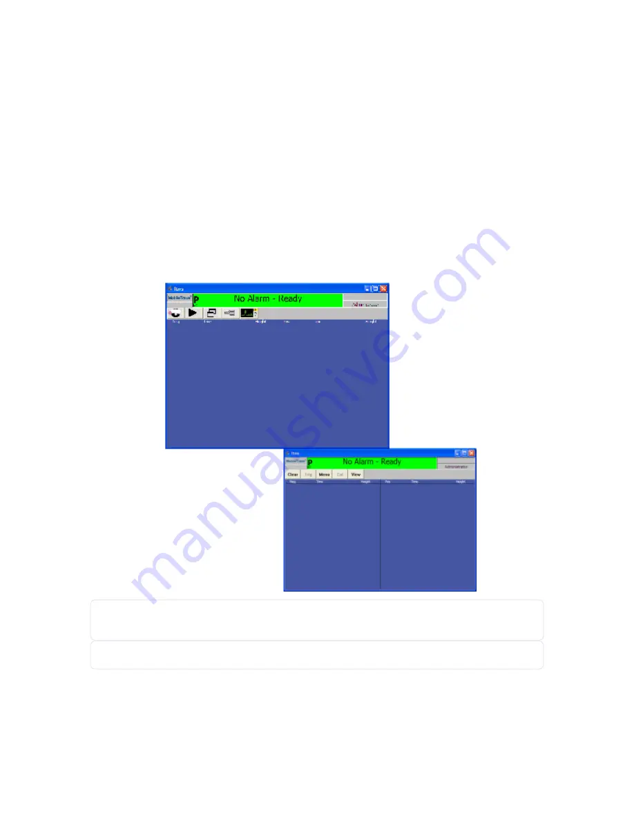
Desktop Application Main Screen

On the

Main screen, there are three frequently used functions: Clear, Menu, and View. Some functions may not

be available to all user levels.

(

see "Default User Privileges" on page 140)

Figure 8-1

Main desktop application screen

NOTE:

To resize the desktop application

Main

screen, place the cursor on the corner of the window and

drag to the desired size.

NOTE:

To toggle between words and icon buttons, press I on the keyboard.

136

Rapiscan Systems Proprietary and Confidential

CHAPTER 8 │ User's Guide

Summary of Contents for Mobile Trace

Page 1: ...MobileTrace User s Guide For P0007027 MA001133 Revision ...

Page 2: ......

Page 3: ...ndeavored to ensure that the information in this manual is comprehensive and accurate as of the date of publication The product you have purchased may contain features not covered by this manual If you have questions about this manual or the product you have purchased please contact Rapiscan Systems Customer Service ...

Page 4: ... Software Installed 2 Related Documentation 2 Before You Begin 2 Major Components 3 Touchscreen 3 Navigation Pad and Control Buttons 3 Stylus and Stylus Holder 4 Desorber and Desorber Cover 4 Filter Pump Cover 4 Battery Compartment and Main Battery 5 Battery Handling 5 Battery Storage 5 Battery Disposal 5 Rear Panel 6 Device Specifications 7 Weight and Dimensions 9 Power Requirements 9 Custom Libr...

Page 5: ...Recharge Time 21 LED Indication 21 Installing the Battery 22 CHAPTER 3 Calibration and Verification Sample Calibration and Verification Traps 24 Calibration Overview 25 Particle Mode 26 Cal Particle Mode 26 Manual Calibrate Particle Mode 28 Dual Peak Calibrate Particle Mode 29 Single Peak Calibrate Particle Mode 33 Set Default Cal Factors 33 Verify Particle Mode 34 Vapor Mode 35 Cal Vapor Mode 35 ...

Page 6: ...es 59 History 60 Add Maintenance Log 61 Export History 61 Copy to USB 61 To a Network or File Location 62 Purge History 63 Status 63 Advanced Menu 64 Adjust Date Time 66 Calibrate Flows 67 Calibrate Touchscreen 68 Calibrate Temperatures 68 Copy Alarm Files to External Media 69 Import User Database 69 Open Alarms Folder 71 Copy Files to USB Storage Device 71 Copy Files to a Shared Network Drive 72 ...

Page 7: ...goff and Power Down 82 Live Mode 83 Verify 83 Help 83 Cancel 84 CHAPTER 5 Analyzing Samples Sampling Matrix 86 Sampling Areas 88 Baggage or Containers 88 Electronic Devices 89 Vehicles 90 Sampling Procedure 91 By Hand Using a Sample Trap 91 By Hand Using a Sample Trap in a Sample Wand 92 By Vapor Sampling Using the Device 94 Removing the Desorber and Installing the Vapor Plate 94 Taking a Vapor Sa...

Page 8: ...105 Resolution 105 Calibration Warning 106 Resolution 106 Heater Warning 106 Resolution 107 Battery Operation Indicators 107 Resolution 108 Low Battery and Backup Battery in Use 108 Resolution 109 Stabilizing Temperature 109 Resolution 110 Change the Dryer Material Reminder 110 Resolution 111 Replace the Membrane Reminder 111 Resolution 112 CHAPTER 7 Maintenance Introduction to Maintenance 114 Shi...

Page 9: ...e Sample Filter 126 Power Up the Device 127 Burn in the Membrane 127 Perform a Calibration and Verification 127 Return to Operation 127 As Needed Maintenance 127 Calibrate the Touchscreen 128 Replace the Fuse 128 Calibrate the Battery 129 Maintenance Logs 130 Shift Maintenance Schedule 130 Weekly Maintenance Schedule 132 Monthly Maintenance Schedule 133 As Needed Maintenance Schedule 134 CHAPTER 8...

Page 10: ...m the Device Application 145 CHAPTER 9 Parts and Accessories Device and Replacement Part Numbers 148 CHAPTER 10 Service and Support Technical Support 152 Customer Service 152 Rapiscan Systems Locations 153 Rapiscan Systems International Locations 153 Warranty Information 153 Consumables 154 INDEX vii Rapiscan Systems Proprietary and Confidential ...

Page 11: ...This page intentionally left blank to ensure new chapters start on right odd number pages CONTENTS User s Guide Rapiscan Systems Proprietary and Confidential ...

Page 12: ...basic knowledge of Explosive and narcotic trace detection Your organization s alarm resolution protocols Read these instructions and all ancillary documentation entirely before installing or operating the device The most current versions of this and related documentation are available through Rapiscan Systems Customer Service Department For instructions on purchasing additional publications NOTE A...

Page 13: ...s on the computer screen Programming or coding sequences device As used in this manual the word device refers to the MobileTrace Safety Terms and Symbols IMPORTANT This graphic is accompanied by additional information indicating the importance of the details CAUTION User should use care to avoid possible damage to the device This graphic is accompanied by additional information indicating the deta...

Page 14: ...uclear Regulatory Commission USNRC guidelines for safety If a problem is suspected with the detector DO NOT open the detector call Rapiscan Systems s Technical Support Department Then if necessary return the instrument to Rapiscan Systems for service Note that in some countries notification of receipt and registration of the source may be required by the national government body responsible for co...

Page 15: ...rom the ASN your authorization to possess and to use sealed sources the IRSN Institute for Radioprotection and Nuclear Safety who has in parallel received a copy of it will send to the beneficiary of the authorization original forms of red color called Request for the supply of sealed sourced matrix based on the content data of your authorization You will fill this request and send it to Rapiscan ...

Page 16: ...ons CAUTION Customer must comply with all applicable shipping regulations when returning devices CAUTION Dispose of batteries within this product according to local regulations Battery Charger Warnings WARNING Do not expose the charger or power supply to water or liquids This is not a sealed case WARNING Do not open the charger or power supply case No user serviceable parts are inside WARNING Do n...

Page 17: ...al Symbols Symbol Description Network Reset Power USB Direct Current Fuse Battery Power Charging Enter Tab Trigger Table 4 1 Universal symbols PREFACE User s Guide Rapiscan Systems Proprietary and Confidential ...

Page 18: ...CHAPTER 1 Device Overview Product Overview 2 Before You Begin 2 Device Specifications 7 Storage 11 Shipping the Device 13 ...

Page 19: ...Information about the battery or charger see the Inspired Energy CH5000A instruction sheet included with the charger or visit www inspiredenergy com Before You Begin Before you begin using the device Check local and national radiation regulations and preregister the radioactive detector if necessary Furnish a storage facility for all device components Review shipping and handling requirements for ...

Page 20: ... Use the provided stylus to make menu selections Navigation Pad and Control Buttons There are built in navigation buttons and a pad to execute certain ITMS software functions There are two green trigger buttons one is located below the 4 way navigational pad and the other is located on the handle The trigger button located on the handle is for ease of vapor sampling at awkward angles CHAPTER 1 Use...

Page 21: ...the detection slot press one of the green trigger buttons which signals the ITMS software to start an analysis the trap reaches the required temperature in 1 to 2 seconds The desorber vaporizes any particles that have been collected by the sample trap NOTE During continuous use the desorber may become contaminated with low volatile material and should be cleaned weekly see Weekly Maintenance on pa...

Page 22: ...tery in fire Avoid exposing the battery to excessive physical shock or vibration Keep the battery out of the reach of children Do not use any battery that has been damaged in any way Always charge in accordance with the manufacturer s instructions using specified chargers only Do not use modified chargers Battery Storage The main battery packs can be stored from 20 C to 60 C at up to 80 relative h...

Page 23: ...sed to aid in the ionization process of the detector The dopants should be inspected monthly and replaced with new chemical dopants as required see Monthly Maintenance on page 123 Power Button Turns the device on and a green light illuminates or blinks depending upon certain powering conditions Press the power button again to turn the device OFF The green light is not illuminated Solid CPU is powe...

Page 24: ...ta to the network or onto a laptop or PC Fan The fan draws air into the device for cooling WARNING Do not block the flow of air into the fan Fuse DC input fuse T8A250 V is located on the rear panel to the right of the handle Additional fuses are available in the maintenance kit DC Power Connector Enables the device to operate from a DC source 12 18 VDC at 8 A max NOTE The device comes standard wit...

Page 25: ...er battery calibrator Backup Battery Internal 12V NiMH provides up to 10 minutes of power to allow the swapping of the external battery Fan Rear Panel 40 mm 30 PPI filter Display Transflective LCD w Touchscreen 3 5 in 240x320 pixel LCD with resistive touchscreen Fuse 8 A 250 V type T time lag Audio Indicator Piezo alarm Radioactive Source Nickel 63 10 millicuries 370 MBq strength Power Cables AC t...

Page 26: ...requirements Custom Library The MobileTrace is set at the factory with a custom library For more information about managing the custom library and creating an expandable custom library see Substances on page 50 NOTE The table below is for instructional purposes only and may not be representative of your specific configuration settings This is not a complete list of explosive and narcotic substance...

Page 27: ...ed for verification Ephedrine equivalent HMX DNT MDMA TETRYL HMX MORPH Morphine DMNB TETRYL AMPHET HMTD NITRATES HMTD NITRATES Ammonium Nitrate Urea Nitrate HMTD MDA NITRO TAGNT DMNB Ketamine p MNT HMTD Pos CAL particle mode calibration Cocaine equivalent Vapor Neg CAL vapor mode internal calibration p MNT TNT COCAINE Black Powder Various Gun Powders RDX HMX HEROIN Neg CAL Neg Ver THC 10 Rapiscan ...

Page 28: ... verification Ephedrine equivalent NITRATES Ammonium Nitrate Urea Nitrate AMPHET MDMA DMNB MDA MORPH Morphine Neg CAL particle mode calibration TNT equivalent EDME AMPHET Vapor Pos CAL vapor mode internal calibration MDA Ketamine Pos CAL particle mode calibration cocaine equivalent Default sample time 10 0 seconds Default sample time 11 0 seconds Default sample time 10 0 seconds Storage This secti...

Page 29: ... where the device location is at room temperature 30 C Product life may vary depending on the environment and device uptime Table 1 7 Negative ion dopant storage and product life Dichloromethane Shelf Life Calculated Storage Conditions Nominal Storage Temp C Fully depleted after 7 2 years Freezer 0 C Fully depleted after 7 5 months Room temperature 24 C Table 1 8 Positive ion dopant storage and sh...

Page 30: ...ipping the Device We require you to follow these procedures in compliance with International Federal State and Local shipping regulations to ensure the safety of shippers and Rapiscan Systems service personnel Read and complete these procedures before returning your Rapiscan Systems MobileTrace for servicing The MobileTrace needs to cool for at least 30 minutes and MUST be placed into its original...

Page 31: ...This page intentionally left blank to ensure new chapters start on right odd number pages ...

Page 32: ...ming Initial Setup 16 Receiving the Device 16 Receiving and Installing Dopants 16 BHT Vapor Mode Calibration Tube 18 Powering Up the Device 18 Logging On to the Device 18 Warm Up Time 19 Charging the Batteries 20 Installing the Battery 22 ...

Page 33: ...or damage to the device that occurred during shipping and only furnishes replacement parts against a written purchase order It is the purchaser s responsibility to file a claim with the carrier Receiving and Installing Dopants The negative and positive ion dopant replacements are shipped separately from the device and in accordance with standard U S Department of Transportation DOT and Internation...

Page 34: ...tely 2 3 full at 2ml by design and to be compliant with DOT shipping regulations 2 Verify the device power is OFF 3 Unscrew the dopant chamber end cap 4 Insert the dopant tubes into the dopant chamber NOTE The BHT tube is already installed the dopant chamber For information on the BHT tube see BHT Vapor Mode Calibration Tube on the next page 5 Replace the dopant chamber end cap CHAPTER 2 User s Gu...

Page 35: ...nnectors and pushing them together until fully engaged Plug the power cord into the power supply and the other end into an AC electrical outlet supplying 90 264 VAC 47 63 Hz Plug the vehicle power adapter into the rear panel by aligning the red dots on the two mating connectors and push them together until fully engaged Plug the other end into a 12 VDC which provides the appropriate power with the...

Page 36: ...nts into the detector itself Once the device is powered ON such contamination slowly vaporizes due to the high operating temperatures and is swept out of the detector device Do not calibrate or analyze samples with the device until after a 24 hour system burn process This ensures that any low volatility contaminants have been purged see Device Burn on page 74 COLD START Off for more than 72 hours ...

Page 37: ...n batteries Rapiscan Systems recommends periodically using the battery charger to check battery status and perform recalibration as needed NOTE Use only the battery charger specified by Rapiscan Systems Place the battery charger on a flat level surface away from sources of heat and moisture Plug the DC connector from the power supply into the back of the charger and connect the power supply to the...

Page 38: ... Ion 4 1 2 hours 9 hours 13 6 hours LED Indication The status of the battery is indicated by the LEDs visible in the status window Color Description Status Green flashing Battery charging Green solid Battery fully charged Blue flashing Battery in calibration mode Table 2 3 Battery charger LEDs CHAPTER 2 User s Guide 21 Rapiscan Systems Proprietary and Confidential ...

Page 39: ...Battery 1 Rotate the battery compartment door latch clock wise to open the device s battery compartment 2 Insert the battery into the rear of the device ensuring the tab displays on the bottom right of the battery 3 Close the battery compartment door latch turning counter clock wise 22 Rapiscan Systems Proprietary and Confidential CHAPTER 2 User s Guide ...

Page 40: ...CHAPTER 3 Calibration and Verification Sample Calibration and Verification Traps 24 Calibration Overview 25 Particle Mode 26 Vapor Mode 35 ...

Page 41: ...The sample traps are also used during the clearing process The calibration traps are used for calibrating the device and are marked with a C at the handle end of the calibration trap Similarly the verification traps are used for verifying the calibration and are marked with a V at the handle end of the verification trap The tapered ends are inserted into the desorber for analysis Handle sample cal...

Page 42: ...shipment minimum 24 C Once then must be discarded Verification trap 6 months from date of shipment minimum Check the Best Used By date on the bottom of the package Table 3 2 Calibration and verification trap shelf life IMPORTANT Store all sample calibration and verification traps in a cool or dry location to ensure shelf life is not com promised After removing sample calibration or verification tr...

Page 43: ...ntroduced For assistance ordering consumables The Calibration Warning message displays every 8 hours by default indicating the device needs routine calibration However additional calibration may be required if the device configuration is modified Particle Mode NOTE You cannot perform a calibration if any warning s other than the Calibration Warning displays Cal Particle Mode 1 Press Cal A message ...

Page 44: ... used by the recognition algorithm to identify substances of interest The peak values display Figure 3 3 Particle Auto calibration window 5 Remove the calibration trap and discard it immediately CAUTION A calibration trap MUST be used only once and then discarded immediately after the calibration is performed 6 Press OK The device alarms on TNT in Explosives mode or Cocaine in Narcotics mode The E...

Page 45: ...nds that you verify the successful calibration see Verify Particle Mode on page 34 NOTE Peak positions on the plasmagram may differ from location to location because different elevations above sea level affect the pressure in the detector Pressure changes can also occur from day to day but these have only a very small effect on the peak positions in the plasmagram Manual Calibrate Particle Mode En...

Page 46: ...below the auto calibration peak height requirements 1 Select Menu Manual Calibrate Figure 3 5 Calibrate Options Dialog 2 Press Dual Peak Calibrate A message to select the calibration substance displays Figure 3 6 Particle Select Neg CAL 3 Verify Neg CAL is selected from the list of substances 4 Press OK A message displays to insert a calibration trap 5 Wearing clean cotton gloves remove a calibrat...

Page 47: ... the Neg CAL peak NOTE The peak selected MUST be the correct peak To determine this you must be aware of where the Neg CAL peak should be located In most cases the peak falls in the white highlighted window If the peak is outside the white window select it and press Yes to accept the selection You must Set Default Cal Factors before you can verify the successful calibration see Set Default Cal Fac...

Page 48: ...s OK A message displays to select the correct peak Figure 3 10 Particle Pos CAL peak 14 Observe the Pos CAL peak in the white window Touch slightly above the top of the peak until the dot drift time and peak height display CHAPTER 3 User s Guide 31 Rapiscan Systems Proprietary and Confidential ...

Page 49: ...ify the successful calibration see Set Default Cal Factors on the facing page This shifts the white window to be centered around the newly selected peak 15 Press OK A message display verifying you want to calibrate the peaks 16 Press Yes A message displays the device has been calibrated 17 Press OK Figure 3 12 Particle Calibration Explosives Detected The device alarms on TNT in Explosives mode or ...

Page 50: ...n routine follows the same principle as the dual peak calibration except only one screen is shown for substance selection The list contains all the explosives and narcotics in the substance file You select only one substance Neg CAL or Pos CAL to calibrate on and then select its appropriate peak Once the calibration is complete Rapiscan Systems recommends you verify the successful calibration For ...

Page 51: ...rmed 6 Press OK The device alarms on RDX HMX in Explosives mode or Ephedrine in Narcotics mode The Explosives Detected or Drugs Detected message displays Figure 3 13 Particle Verification Explosives Detected If the Verification Failed message displays test the verification trap as a sample The device should alarm on RDX HMX in Explosives mode or Ephedrine in Narcotics mode If the alarm displays th...

Page 52: ...er the device 3 Press Trig the green button on the navigation pad or the green button on the device handle to start the collection process The peak values display 4 Press OK A message displays to press Clear 5 Press Clear The device begins the clearing process and the No Alarm Ready message displays 6 Once the calibration is complete Rapiscan Systems recommends that you verify the successful calib...

Page 53: ...the vapor plate see Removing the Desorber and Installing the Vapor Plate on page 94 2 Select Menu Manual Calibrate Figure 3 14 Vapor Calibrate Options Dialog 3 Press Dual Peak Calibrate A message to select the calibration substance displays Figure 3 15 Vapor Select a substance to calibrate on neg 4 Select a substance from the negative ion list of substances If you want to calibrate using the inter...

Page 54: ... to place the device next to the sub stance because the internal calibrant is stored in the dopant chamber 7 Press Yes 8 If you selected Vapor Neg CAL collect for 1 second and press Stop A substance other than Vapor Neg CAL collect for 5 10 seconds and press Stop A message displays to select the correct peak Figure 3 17 Vapor Neg CAL peak 9 Verify the calibration peak displays in the white window ...

Page 55: ...e than one small hole in the BHT tube If there is a small hole present in the BHT tube repeat the manual calibration steps using the Check Sample Vial 11 Touch slightly above the top of the peak until the dot drift time and peak height display Figure 3 18 Vapor Select Neg CAL peak NOTE The peak selected MUST be the correct peak To determine this you must be aware of where the Neg CAL peak should b...

Page 56: ...select Vapor Pos Ver To calibrate using one of the substances in the list select the appropriate substance 14 Press OK A message displays to select the correct peak Figure 3 20 Vapor Vapor Pos CAL peak 15 Verify the calibration peak displays in the white window 16 Touch slightly above the top of the peak until the dot drift time and peak height display CHAPTER 3 User s Guide 39 Rapiscan Systems Pr...

Page 57: ...e the device has been calibrated displays 19 Press OK 20 Press Clear The device begins the clearing process and the No Alarm Ready message displays 21 Once the calibration is complete Rapiscan Systems recommends that you verify the successful calibration see Verify Vapor Mode below NOTE If the peak was outside the white window you need to Set Default Cal Factors before you can verify the successfu...

Page 58: ...u were analyzing a sample Therefore select Menu Verify to exit out of Verification Mode Place the sample in front of the vapor plate leaving a small space between the sample and vapor plate 3 Press Trig the green button on the navigation pad or the green button on the device handle to start the collection process Figure 3 22 Vapor Using Check Sample vial 4 Collect the sample for 10 seconds 5 Press...

Page 59: ...DNT and Ephedrine The Contraband Detected message displays 7 Press Clear The device begins the clearing process and the No Alarm Ready message displays 42 Rapiscan Systems Proprietary and Confidential CHAPTER 3 User s Guide ...

Page 60: ...CHAPTER 4 Menu Functions Main Screen 44 Menu Functions 45 ...

Page 61: ...ter buttons on the device Any buttons that are greyed out are not accessible by the level of the current user For information about user levels see Default User Privileges on page 55 Figure 4 1 Main screen Figure 4 2 Main screen icons Status Bar Color Description Green Device ready Yellow Warnings and Diagnostics Red Alarm Table 4 1 Status bar indicators 44 Rapiscan Systems Proprietary and Confide...

Page 62: ...age 55 Cal Initiates an auto calibration procedure see Calibration and Verification on page 23 View Enables you to select the Peaks Plasmagram Select Scan Intensity Map or 3 D view mode see Selecting View Modes on page 98 Data Enables you to scroll between ION ION and ION NOTE This button is available in the Plasmagram Intensity Map and 3 D view modes only see Selecting View Modes on page 98 Table...

Page 63: ...vel user a message displays verifying you want to open the advanced recall screen Continue with see Step 2 Figure 4 4 Advanced recall If you are logged on as a Maintenance level user the simplified recall screen displays the alarm or signal files stored on the hard disk in the form of sca files Go to see Step 3 46 Rapiscan Systems Proprietary and Confidential CHAPTER 4 User s Guide ...

Page 64: ...bration and verification file names display in the status bar when the device is being calibrated or when the calibration is being verified Press No to open the simplified recall screen 3 Do one of the following In the advanced recall screen double click the desired file If you want to recall an archived file navigate up one level to Storage Card ITI ITMSWIN Alarms Archive mm dd yyyy and double cl...

Page 65: ...0001 for alarms incrementing by one for each file saved NOTE When assigning a filename do not use the following symbols Also use a dash or hyphen and underscore _ be used in place of a space or period 4 Press OK A message displays to enter a note about the file 5 Press Show Hide Keyboard 6 Touch in the text entry window to place the cursor there then use the keyboard to enter a brief note about th...

Page 66: ... Sets the percentage of programmed alarm level required before a substance is identified and reported Full Screen View in S Scan Displays the substance name or code on a flashing screen in Select Scan view The screen flashes until the Clear button is pressed Display Alarm Str in S Scan Determines how the strength of the detected substance displays in Select Scan view When this box is checked the s...

Page 67: ... of data to be used Never Every Alarm or Every Sample NOTE Only one of the three buttons can be selected If the device should Prompt for Name for the file being saved and Prompt for Notes when automatically saving data in the Every Alarm and Every Sample options NOTE Both boxes may be checked for these options NOTE Whenever the Prompt for Name or Prompt for Notes screen box displays you are given ...

Page 68: ...ances Figure 4 8 Substance Selection Select and Deselect 1 Select Menu Substances 2 Highlight the name on the list you want to select or deselect 3 Do one the following Click the Sel check box to select the substance The column labeled Sel displays yes for that substance Unclick the Sel check box to deselect the substance A message displays verifying you want to turn off the substance Press Yes Th...

Page 69: ...iability for adding substances Figure 4 9 ITMS WARNING 3 Review the terms and conditions and press OK NOTE If you do not agree with the terms and conditions press Cancel Figure 4 10 Secondary Substance Selection 4 Press the keyboard icon to display the keyboard 5 Enter a Name Code and Notes using the keyboard NOTE You cannot use duplicate substance names Each substance name must be unique 52 Rapis...

Page 70: ...ese fields should be configured with support from Rapiscan Systems Technical Support see Technical Support on page 152 11 Press OK until the Substance Selection screen displays The newly added substance displays at the bottom of the list with a white background to separate any added substances from the custom library Figure 4 12 Primary Substance Selection substance added 12 Press OK until you ret...

Page 71: ... keyboard modify the fields as necessary NOTE These fields should be modified with support from Rapiscan Systems Technical Support see Technical Support on page 152 5 Press OK until you return to the Main screen Delete 1 Select Menu Substances 2 Highlight the substance you want to delete NOTE You cannot modify or delete substances from the custom library You can only modify and delete substances t...

Page 72: ...r added security the default pass words should be changed during the training session Default User Privileges The following table lists the various functions that are available on the MobileTrace and which user level has access to them It is based on the software defaults that are shipped from the factory Function Shortcut Key Operator Maintenance Administrator Main Screen Clear ü ü ü Trig ü ü Men...

Page 73: ...rn In Membrane ü ü Exit Standby Alt X Standby Hibernate Only Standby Hibernate Only ü Change Mode ü Print ü ü ü Change Language ALT L ü ü Logoff ü ü ü Live Mode Ctrl L ü ü Verify ü ü ü Help F1 ü ü ü Cancel Esc ü ü ü Advanced Menu Functions Ctrl N Adjust Date Time ü Advanced Configuration Calibrate Flows ü Calibrate Temperatures ü Calibrate Touchscreen ü 56 Rapiscan Systems Proprietary and Confiden...

Page 74: ...onfig Factory ü Restore Default Users ü Set Default Cal Factors Ctrl F Shortcut Key Only ü Set User Privileges Alt P ü Show Network Name and IP ü Startup Options Device Burn ü Upgrade Software Alt U ü User Defined Warnings ü Keystroke Function Restore a saved config from config sav Ctrl R ü Manipulation of the configuration is not recommended Add NOTE You cannot have more than 500 users 1 Select M...

Page 75: ...er The Password must be at least four 4 digits 5 Assign the appropriate user privilege level 6 Press OK The newly added user displays in the Users list Figure 4 14 Newly added user 7 Press Close Modify 1 Select Menu Users 2 Highlight the user you want to modify 58 Rapiscan Systems Proprietary and Confidential CHAPTER 4 User s Guide ...

Page 76: ... 5 Press Close Config Notes Displays the device configuration various device settings and notes that have been added for the given file To view a recalled file Notes information select Menu Config Notes To view the substance configuration press the Substance Config tab Figure 4 15 Config Notes NOTE Only substances for the existing detection mode that are selected for detection display in Config No...

Page 77: ...ibed below Function Description Main Window Lists all the events that occurred on the device Use the scroll bar to see the entire list in the Main Window Statistics Window Lists user actions for the date range selected from the last time the device was powered on View Detail Displays the entry detail NOTE You must first highlight the appropriate entry in the Main Window Show Samples or Show File S...

Page 78: ...tory files to a USB storage device or to a network or file location The file is exported as serial csv the comma separated values format which can be opened by any application that reads csv files such as Microsoft Excel The files also can be exported to a network or file location automatically at a specified time of day Copy to USB 1 Select Menu History 2 Insert the USB storage device into the US...

Page 79: ...d to your network via the Ethernet port 2 Select the From and Through dates 3 Press Export History The Export History screen displays 4 Click the keyboard icon 5 Enter the networked computer name and shared folder location in the address bar For example enter ComputerName SharedFolder 6 If the folder is password protected enter the user name and password you use to log on to your computer 7 Do one...

Page 80: ... message displays asking if you want to remove all data files stored in Storage Card ITI ITMSWIN alarms before date MM DD YYYY Continue with see Step 4 Press No to cancel the operation 4 Do one of the following Press Yes to remove the data files and history files then press OK A message displays the number of data files that were removed Press No to keep the data files 5 Press Close Status Display...

Page 81: ...t are not accessible by the level of the current user Figure 4 20 Advanced Menu screens Function Description Adjust Date Time Sets the device date and time see Adjust Date Time on page 66 Advanced Configuration Provides options to configure adjust the data view primary mode of operation sample pump and trigger mode Table 4 7 Advanced Menu functions 64 Rapiscan Systems Proprietary and Confidential ...

Page 82: ...older NOTE This function does not remove archived files To remove archived files select Advanced Menu Open Alarms Folder Navigate up one level Select the appropriate archived folder and remove it Delete All bin Settings Files Restores all the configuration files to the factory defaults This would include all substance configurations users history files alarm files and privilege settings Import Use...

Page 83: ...of the device due to contamination You can select one of the following device burn times 2 seconds 2 5 10 15 20 30 or 45 minutes 1 24 or 48 hours The device heats clean cools and stabilizes see Device Burn on page 74 Upgrade Software Upgrades device software with latest version from a CD using the desktop application software or from a USB storage device inserted into USB port on the rear panel se...

Page 84: ...ning class This function should not be performed without a full understanding of what is being changed as it can render the device inoperable It may resolve a warning but could also be masking another problem 1 Select Menu Advanced Menu Page 2 2 Press Calibrate Flows A message displays verifying you want to calibrate flows 3 Press Yes Figure 4 22 Flow Calibration 4 Modify the fields as necessary C...

Page 85: ...en Once complete a message to accept the new settings displays 6 Press Enter Calibrate Temperatures Step by step instruction is taught during the hands on training class This function should not be performed without a full understanding of what is being changed as it can render the device inoperable It may resolve a warning but could also be masking another problem 1 Select Menu Advanced Menu Page...

Page 86: ...es copied 4 Press OK For information about copying specific files or archived files see Copy Files to USB Storage Device on page 71 or see Copy Files to a Shared Network Drive on page 72 Import User Database Enables you to import a file containing a user database user names PINs and privilege levels for up to 500 users in comma separated value format csv from an external spreadsheet such as Micros...

Page 87: ...of the device 3 Select Menu Advanced Menu 4 Press Import User Database A message displays verifying you want to import a user database 5 Press Yes The Enter File Name and Location screen displays 6 Verify the path is correct where Hard Disk is the Root level of the external media or enter a new path for the user database filename and location 7 Press OK A warning message displays that all users ar...

Page 88: ...9 Press OK The software restarts and you must log back into the device Open Alarms Folder Copy Files to USB Storage Device 1 Select Menu Advanced Menu Open Alarms Folder Figure 4 27 Open alarms folder 2 Select the file or files you want to copy CHAPTER 4 User s Guide 71 Rapiscan Systems Proprietary and Confidential ...

Page 89: ...on the tool bar to hide the menu 5 Insert the USB storage device into the USB port on the rear panel A Hard Disk icon displays 6 Double click My Device 7 Double click Hard Disk 8 Select Edit Paste to copy the file onto the USB storage device Once you copy the file s to the USB storage device Rapiscan Systems recommends you delete the files from the device For more information see Delete Alarm File...

Page 90: ...and shared folder location in the address bar For example enter ComputerName SharedFolder 6 Press Enter NOTE If the folder is password protected enter the user name and password you use to log on to your desktop computer 7 Select Edit Paste Once you copy the file s to the USB storage device Rapiscan Systems recommends you delete the files from the device For more information see Delete Alarm Files...

Page 91: ...n changes displays Figure 4 30 Config changes 3 Note any configuration changes that you would like to add back into the library once the substances are returned to their defaults 4 Press Close A message displays verifying you want to restore the default substance configuration 5 Press Yes A message displays asking if you want to restore all other configuration 6 Press Yes or No as appropriate NOTE...

Page 92: ...ime displays and counts down c The cooling process occurs d The temperatures stabilize NOTE You can cancel a Device Burn at any time When a Device Burn is canceled it is logged into the history file Set User Privileges 1 Select Menu Advanced Menu 2 Press Set User Privileges A screen with the privilege level options displays CHAPTER 4 User s Guide 75 Rapiscan Systems Proprietary and Confidential ...

Page 93: ...ecutable file s exe and supporting library files dll are within the RapiscanSystems folder on the root directory of the software upgrade CD 3 Copy the RapiscanSystems folder from the software upgrade CD to the root directory of the USB storage device 4 Verify the RapiscanSystems folder and all its subordinating are on the root directory of the USB storage device 5 Remove the USB storage device and...

Page 94: ...re and sample time configuration to the software defaults 10 Press Yes A message displays the default configuration has been restored 11 Press OK The Log On screen displays User Defined Warnings 1 Select Menu Advanced Menu Page 2 2 Press User Defined Warnings Figure 4 33 User Defined Warnings 3 Do one the following Check the Warning Alarm button for which you want to modify its message The current...

Page 95: ...file to the MobileTrace Data directory The File Copied message displays 5 Press OK Import 1 Verify the UserMessages bin file is located within the MobileTrace Data folder on the root directory of the USB storage device NOTE The file must be within a folder labeled MobileTraceData folder on the root directory of the USB stor age device in order for the file to import correctly 2 Insert the USB stor...

Page 96: ...Select Menu Exit Standby Figure 4 34 Exit Standby 2 Press one of the following Exit ITMS to exit the ITMS software to the Windows desktop Standby to put the device in standby mode Standby mode is a battery saving mode that can be instantly restored to take samples Standby saves approximately 5 10 of the battery life Hibernate to put the device in hibernation mode Hibernate mode manipulates the pow...

Page 97: ...h as TATP appear in the Positive Ion window even though they are explosives Narcotics Optimized Mode When Narcotics Optimized mode is selected only the narcotics substances are selected by default for analysis The ITMS software sets the detector temperature at 205ºC which is the ideal temperature setting for the detection of narcotics The split window is displayed but all narcotics appear in the P...

Page 98: ...cription Print Data Config Prints the plasmagram with peaks peaks found list any substances detected and the device and substance configuration Print Data Prints the plasmagram with peaks peaks found list and any substances detected Print Config Prints the device and substance configuration Table 4 8 Printing Dialog If you did not check Show Printer Options the data prints to the default local or ...

Page 99: ...may appear in the local language selected 1 Select Menu Change Language 2 Select the language 3 Press OK Logoff and Power Down Enables you to log off of the ITMS software Rapiscan Systems recommends you log off the ITMS software when not in use 1 Select Menu Logoff If you are powering down the device continue with see Step 2 2 Press the power button so the device is OFF If the device is being pack...

Page 100: ...Press Menu Live Mode again to turn Live Mode off Verify Enables you to verify the calibration routine was successful see Calibration and Verification on page 23 Help Enables you to view any warnings that display on the device and provides steps to perform routine calibration verification and sampling 1 Do one of the following Select Menu Help Press the status bar in the main window CHAPTER 4 User ...

Page 101: ...Figure 4 39 Help screen 2 Press Close Cancel Closes the Menu and brings you back to the Main screen 84 Rapiscan Systems Proprietary and Confidential CHAPTER 4 User s Guide ...

Page 102: ...CHAPTER 5 Analyzing Samples Sampling Matrix 86 Sampling Areas 88 Sampling Procedure 91 Sampling Sequence 97 Clearing an Alarm 97 Selecting View Modes 98 ...

Page 103: ...obability of being detected in vapor mode See see Table 5 1 The vapor method should be selected to allow lower alarm levels and manual control of the sampling pump The operator should locate a vapor release point on the suspect item and while ensuring not to make physical contact hold the device s desorber close to this point The operator should then press and hold for 8 10 seconds to draw in vapo...

Page 104: ...okeless Powders Winchester Blue Dot ü ü ü Both Yes Yes TATP ü ü ü Vapor ü Particle Yes Yes PETN ü ü Yes DNT ü ü ü No Yes HMX ü ü Yes No TETRYL ü ü ü Both No No NITRATES HMTD NITRATES Ammonium Nitrate Urea Nitrate HMTD ü ü ü Both Yes Yes HMTD ü ü ü Vapor ü Particle Yes Yes Black Powder Various Gun Powders ü ü No TAGGANTS p MNT ü ü Vapor ü Particle No No DMNB ü ü Vapor ü Particle Yes No Narcotics Mo...

Page 105: ...ted Selected METHAM ü ü ü Yes Yes EPHEDRINE ü ü ü No Yes MDMA ü ü ü Yes No MORPH Morphine ü ü Yes No AMPHET ü ü Yes Yes MDA ü ü ü Yes No Ketamine ü ü EDME ü ü Yes Sampling Areas Baggage or Containers To sample baggage and containers wipe the following Outside of item Zipper tabs Closure flaps Latches Handles and straps 88 Rapiscan Systems Proprietary and Confidential CHAPTER 5 User s Guide ...

Page 106: ...sample electronic devices wipe the following Vents Seams Battery compartments Disk drives Edges Latches Touch pads CAUTION Do not wipe sample traps across surfaces such as computer screens cell phone displays camera lenses as it may damage the surface CHAPTER 5 User s Guide 89 Rapiscan Systems Proprietary and Confidential ...

Page 107: ...To sample vehicles wipe the following Door handle Gas cap Steering wheel Knobs Seat belts Luggage Wherever there may be a fingerprint NOTE Use a separate clean sample trap for each vehicle being sampled 90 Rapiscan Systems Proprietary and Confidential CHAPTER 5 User s Guide ...

Page 108: ...ns The No Alarm Ready screen must display in the status bar for sampling operations to occur IMPORTANT Always wear clean cotton gloves supplied with the device when handling sample calibration or veri fication traps Gloves reduce the transfer of finger oils and other contaminants By Hand Using a Sample Trap 1 Wearing clean cotton gloves remove a sample trap from the package or use an existing clea...

Page 109: ...mple Wand The sample wand is used to sample in hard to reach areas and to protect the safety of the operator The sample trap is inserted into the clip portion of the sample wand Proper installation ensures that the sample trap stays in place 1 Wearing clean cotton gloves remove a sample trap from the package or use an existing clean sample trap that has not exceeded its sampling events 2 If you ob...

Page 110: ...last 9 Press the button and remove the sample trap from the sample wand 10 Immediately insert the sample trap into the desorber 11 Press Trig the green button on the navigation pad or the green button on the device handle The device automatically analyzes the sample If an alarm is detected a message displays in the status bar see Alarm on page 97 Discard the sample trap immediately and follow your...

Page 111: ...e 1 Press the power switch on the rear of the device to turn the device OFF 2 Pull the metal rings apart and lift the desorber cover to remove it Figure 5 7 Removing desorber cover 3 Unscrew the retaining ring to remove the desorber Leave the white seal disc in place Figure 5 8 Removing retaining ring and desorber 4 Place the vapor plate inside the locking ring 94 Rapiscan Systems Proprietary and ...

Page 112: ...e alignment pin on the device Figure 5 10 Seal disc detail 6 Screw on the locking ring to hold on the vapor plate Do not overtighten Figure 5 11 Vapor plate installed 7 Press the power switch on the rear of the device to turn the device ON CHAPTER 5 User s Guide 95 Rapiscan Systems Proprietary and Confidential ...

Page 113: ...perature Taking a Vapor Sample 1 Place the vapor plate as close to the object being sampled without touching preferably around seams or areas where vapors may seep out Figure 5 12 Vapor sampling 2 Press Trig the green button on the navigation pad or the green button on the device handle 3 Collect a vapor sample for 8 10 seconds 4 Press Stop to stop the collection process 96 Rapiscan Systems Propri...

Page 114: ...etected Clearing an Alarm Always follow your organization s alarm resolution protocol Alarms are automatically saved as long as the default Options settings have not been changed 1 Press Clear The device begins the clearing process and displays the status bar messages shown below 2 Follow the messages to clear the device a Clearing b Sampling NOTE For some substances additional steps may be needed...

Page 115: ...ts cooling down 3 Wearing clean cotton gloves remove a sample trap from the package or use an existing clean sample trap that has not exceeded its sampling events 4 If you obtained a sample trap from the package close the cover immediately to avoid contamination 5 Insert a sample trap into the desorber 6 Press Trig the green button on the navigation pad or the green button on the device handle The...

Page 116: ...d list shows the alarming substance s and gives the location time and the strength of the alarm The strength value is a multiple of the alarm level as calculated by the software It does not necessarily indicate the quantity of the substance detected Upon touching the top of any peak a red dot displays and the peak is highlighted in red to the left in the peaks found list The plasmagram highlights ...

Page 117: ...on menu Press and drag to define diagonal corners of the zoom region To return to the previous zoom press Alt Z To reset the zoom press Ctrl Z Select Scan View The Select Scan view requires no interpretation and provides the fastest sampling throughput To simplify operations and prevent confusion the Select Scan bar graph view displays the selected substances in bar graph form These substances are...

Page 118: ...ent a sequence of peaks that can be used to identify a substance Details about the measurement such as mean time maximum and minimum height and slope can be displayed by touching the line of the detected desired peak To access the Intensity Map view select View Intensity Map To view the Intensity Map for the positive negative or both modes select Data ION ION or ION Figure 5 17 Intensity Map view ...

Page 119: ...magram looked like as it moved through time The green line represents the sequence of peaks detected during the default 120 scans To access the 3 D view select View 3 D from the Main screen To view the 3 D view for the positive negative or both modes select Data ION ION or ION on the Main screen Figure 5 18 Processed 3 D view For information about how to navigate the plasmagram in 3 D view see Nav...

Page 120: ...Flow Warning 104 Sample Flow Warning 105 Calibration Warning 106 Heater Warning 106 Battery Operation Indicators 107 Low Battery and Backup Battery in Use 108 Stabilizing Temperature 109 Change the Dryer Material Reminder 110 Replace the Membrane Reminder 111 ...

Page 121: ...e fault and troubleshooting tips to resolve the warning If multiple warning conditions exist the highest priority warning displays in the status bar and all warnings are detailed in the message The History menu function also provides additional information when diagnosing warnings Detector Flow Warning The Detector Flow Warning indicates the detector flow is outside the calibrated range or the des...

Page 122: ...utside the calibrated range Figure 6 3 Sample Flow Warning Resolution 1 Touch the warning on the status bar to display the warning details Figure 6 4 Sample Flow Warning details 2 Press Close 3 Verify that routine maintenance has been performed If routine maintenance has not been done perform maintenance 4 If the warning is not resolved contact your technical support person or Rapiscan Systems Tec...

Page 123: ... display the warning details Figure 6 6 Calibration Warning details 2 Press Close 3 Select Menu Manual Calibrate or press Cal to calibrate the device see Calibration and Verification on page 23 Heater Warning The Heater Warning indicates there could be a problem with the internal heater due to a short circuit in the temperature sensor wiring or open wiring 106 Rapiscan Systems Proprietary and Conf...

Page 124: ...icators The battery operation icon displays in the top left corner of the touchscreen when the device is operating on battery power The power plug icon displays when the device is running from AC power When connected to AC power the battery will be trickle charged WARNING The device can run on battery power for up to 4 hours Always have a second battery charging on the charger so that when the bat...

Page 125: ... Low Battery and Backup Battery in Use The yellow battery icon indicates the main battery is running below 10 of full capacity Figure 6 10 Low battery icon The red battery icon and Backup Battery in Use warning indicate the main battery power has been switched to the backup battery Figure 6 11 Battery Backup in Use icon If the backup battery is low and the external battery is removed the Backup Ba...

Page 126: ...3 Swap the low battery with a fully charged battery plug in the AC power supply or shut down the device Stabilizing Temperature The Stabilizing Temperature warning indicates the temperatures are stabilizing This warning displays when the device is warming up or the detection mode has been changed CHAPTER 6 User s Guide 109 Rapiscan Systems Proprietary and Confidential ...

Page 127: ...f this warning displays for more than 40 minutes or if the temperatures differ more than the limits indicated on the Status screen contact your technical support person or Rapiscan Systems Technical Support see Technical Support on page 152 Change the Dryer Material Reminder This message reminds you the dryer material must be replaced weekly NOTE In extremely humid conditions it may be necessary t...

Page 128: ...the membrane must be replaced monthly NOTE The membrane is cleaned and inspected weekly as part of the weekly maintenance and should be replaced monthly as part of monthly maintenance If it is torn punctured incorrectly aligned dirty or damaged it must be replaced sooner Figure 6 18 Replace membrane reminder CHAPTER 6 User s Guide 111 Rapiscan Systems Proprietary and Confidential ...

Page 129: ...Resolution Replace the membrane see Replace the Membrane on page 124 112 Rapiscan Systems Proprietary and Confidential CHAPTER 6 User s Guide ...

Page 130: ...CHAPTER 7 Maintenance Introduction to Maintenance 114 Shift Maintenance 114 Weekly Maintenance 116 Monthly Maintenance 123 As Needed Maintenance 127 Maintenance Logs 130 ...

Page 131: ...ance You may need the following tools not provided by Rapiscan Systems Flathead screwdriver Phillips head screwdriver Needle nose pliers Shift Maintenance To keep the device operating at peak performance the procedures listed in this section should be performed at the beginning of every shift NOTE Rapiscan Systems defines a shift as every 8 hours CAUTION When maintaining the device you must wear c...

Page 132: ...alibration and verification trap packages 3 Verify that you have plenty of clean cotton gloves for sample collection and maintenance procedures 4 If necessary contact Customer Service to replenish consumables Perform a Calibration and Verification 1 Log onto the ITMS software 2 Perform a calibration and verification see Calibration and Verification on page 23 3 Ensure there are no alarms or warnin...

Page 133: ...bles parts and supplies NOTE The ability to perform some maintenance procedures may depend upon the privilege levels assigned Power Down the Device 1 Select Menu Logoff 2 Press the power button so the device is OFF and allow the device to cool for 5 10 minutes WARNING Device may be hot You must let the device cool prior to opening the device Clean and Inspect the Membrane 1 Pull the two metal ring...

Page 134: ...al disc to expose the membrane and set aside Figure 7 5 Remove white seal disc 4 Using a Rapiscan Systems supplied alcohol swab gently wipe the membrane Figure 7 6 Wipe membrane CHAPTER 7 User s Guide 117 Rapiscan Systems Proprietary and Confidential ...

Page 135: ...ne on page 124 Clean the Desorber or Vapor Plate 1 Using the Rapiscan Systems supplied canned air blow air into the center hole on the back of the desorber and blow air through the slot on the front of the desorber Figure 7 7 Blow dust and dirt from desorber 2 Using a Rapiscan Systems supplied alcohol swab gently clean the white seal disc and desorber or vapor plate 118 Rapiscan Systems Proprietar...

Page 136: ...ng that it is aligned and seated properly Figure 7 9 Reinstall white seal disc 4 Do one of the following If you are installing the desorber align the desorber pins with the white seal disc and screw on the desorber s retaining ring Continue with see Step 5 CHAPTER 7 User s Guide 119 Rapiscan Systems Proprietary and Confidential ...

Page 137: ...circulating air device that flows through the detector and acts to remove moisture contaminants and other vapors from the air circulating through the detector The water vapor is absorbed in the dryer material and becomes saturated and therefore must be replaced on a weekly basis A message displays reminding you to change the dryer material 1 Remove the dryer tube at the rear of the device by unscr...

Page 138: ...ottle immediately to prevent degradation Each dryer bottle contains enough material for multiple replenishment cycles Refer to the SDS for proper handling 6 Screw on the dryer tube end cap to the dryer tube 7 Inspect the two O rings on the dryer tube and replace if needed Figure 7 13 Dryer tube O rings 8 Reinsert the dryer tube Clean the Fan Air Filter 1 Gently remove without unscrewing the fan gu...

Page 139: ...ace the filter if damaged or torn Power Up the Device Press the power button so the device is ON and allow it to warm up Perform a Calibration and Verification 1 Log onto the ITMS software 2 Perform a calibration and verification see Calibration and Verification on page 23 3 Ensure there are no alarms or warnings 122 Rapiscan Systems Proprietary and Confidential CHAPTER 7 User s Guide ...

Page 140: ... page 116 Check the Dopant Levels The device uses two dopant chemicals to constantly treat the air circulating through the device These chemicals are located inside the dopant chamber on the rear panel The chemicals used are ammonium carbamate positive ion and dichloromethane negative ion The levels of these chemicals should be checked every month to ensure there is solid fluid remaining see Recei...

Page 141: ...r sampling CAUTION Place spare dopants in cold storage in a freezer if possible to extend their life DO NOT store dopants with foodstuffs 4 Insert the dopant tubes into the chamber NOTE Make sure the dopants that may have been stored in the freezer have returned to room temperature before installing in the chamber 5 Clean the O ring on the dopant chamber end cap with an alcohol swab 6 Inspect the ...

Page 142: ...s from the old membrane remains Figure 7 18 Clean inlet 6 Remove a new replacement membrane from its package holding it by its thicker edges 7 Carefully push the new membrane over the inlet NOTE Do not push on the face of the membrane The membrane stretches slightly and then snaps into position NOTE The new membrane installs easier if first wiped with an alcohol swab 8 Carefully reinstall the whit...

Page 143: ...rty or dusty environments you may need to replace the sample filter more often 1 Using a screwdriver unscrew the four screws to remove the filter cover Figure 7 19 Sample filter cover 2 Rotate the right endcap counterclockwise and pull to release it from the tube Figure 7 20 Sample filter 3 Remove the sample filter 4 Inspect the sample filter and do one of the following If the sample filter is vis...

Page 144: ...ion on page 23 2 Ensure there are no alarms or warnings Return to Operation Make all entries in your device s maintenance log as directed by your administrator As Needed Maintenance To keep the device operating at peak performance the procedures listed in this section should be performed as needed CAUTION When maintaining the device you must wear clean cotton gloves and use only Rapiscan Systems s...

Page 145: ... remove the power cord you must grasp it close to the red dots and pull toward you There is a quick disconnect that releases it from the rear panel 4 Turn the fuse holder 1 4 turn with a flathead screwdriver to access the fuse Figure 7 21 Remove old fuse 5 Pull the fuse out and replace with a new one by pushing it in and turning it clockwise 6 Replace the power cord Figure 7 22 Replace fuse 128 Ra...

Page 146: ...fully charged fully calibrated battery The most common cause of calibration failure is overheating of the pack during discharge Keep the charger away from direct sunlight or heat sources Battery Notes What is recalibration and why is it needed The fuel gauge in the battery uses a highly accurate voltmeter ammeter and time clock to measure actual charge in and out of the battery pack In addition th...

Page 147: ...stomer ID ______________________________________ Wear clean cotton gloves during all maintenance procedures Maintenance frequency may require adjustment based on environmental and operational conditions Shift SUN MON TUES WED THUR FRI SAT Clean the Touchscreen 1st 2nd 3rd Check the Supplies 1st 2nd 3rd Perform a Calibration and Verification 1st 2nd 3rd Rapiscan Systems Proprietary and Confidential...

Page 148: ...res Maintenance frequency may require adjustment based on environmental and operational conditions Shift SUN MON TUES WED THUR FRI SAT Return to Operation 1st 2nd 3rd NOTE Shift maintenance must be performed a minimum of once a day 1 Date and initial when action is performed 2 It is recommended you print and save the plasmagram data Rapiscan Systems Proprietary and Confidential CHAPTER 7 User s Gu...

Page 149: ...ional conditions 1st Week 2nd Week 3rd Week 4th Week 5th Week if applicable Power Down Device Clean and Inspect the Membrane Clean the Desorber or Vapor Plate Replace the Dryer Material Clean the Fan Air Filter Power Up the Device Perform a Calibration and Verification Return to Operation NOTE Fifth week column used for a 5 week month 1 Date and initial when action is performed 2 It is recommended...

Page 150: ...ions JAN FEB MAR APR MAY JUNE JULY AUG SEPT OCT NOV DEC Power Down the Device Check the Dopant Levels Replace the Membrane Check the Sample Filter Power Up the Device Burn in the Membrane Perform a Calibration and Verification Return to Operation 1 Verify that shift maintenance and weekly maintenance have been performed before monthly maintenance 2 Date and initial when action is performed 3 It is...

Page 151: ...ocedures Maintenance frequency may require adjustment based on environmental and operational conditions Date Initial Date Initial Date Initial Date Initial Date Initial Date Initial Calibrate the Touchscreen Replace the Fuse Calibrate the Main Battery 1 Date and initial when action is performed 2 It is recommended you print and save the plasmagram data Rapiscan Systems Proprietary and Confidential...

Page 152: ...CHAPTER 8 Desktop Application Connecting to the Device 136 Desktop Application Main Screen 136 Desktop Application Menu Functions 137 ...

Page 153: ...creen there are three frequently used functions Clear Menu and View Some functions may not be available to all user levels see Default User Privileges on page 140 Figure 8 1 Main desktop application screen NOTE To resize the desktop application Main screen place the cursor on the corner of the window and drag to the desired size NOTE To toggle between words and icon buttons press I on the keyboard...

Page 154: ...r a description of each of the Menu functions available in the desktop application see Menu Functions on page 43 Also there are four additional buttons functions in the desktop application Menu screen Figure 8 2 Desktop application Menu functions The following sections describe the functionality in the desktop application that is slightly different from or in addition to the device software Recall...

Page 155: ...uble click ALM00007 the software opens it re analyzes the data and displays the specified alarm file as a plasmagram Figure 8 4 Recalled file NOTE If you are recalling files created with a prior version of software the following message displays Warning This data file is from an older software version and may not display the same results as when it was saved Recall the file with the original softw...

Page 156: ...en and not be labeled Substances Displays and or labels peaks for selected substances if selected Report Level Sets the percentage of programmed alarm level required before a substance is identified and reported Full Screen View in S Scan Displays the substance name or code on a flashing screen in Select Scan view The screen flashes until the Clear button is pressed Display Alarm Str in S Scan Det...

Page 157: ...nu Config Notes For a list of user levels and default user privileges see Default User Privileges below To access the Users screen select Menu Users NOTE Any changes made in the Users screen on the desktop application do not affect the user settings on the device NOTE The factory installed passwords are given out during training For added security the default pass words should be changed during th...

Page 158: ... M File Recall R ü ü Save View Config Notes Alt N ü ü ü History Status Edit Options O ü ü Configuration Substances L ü Users U ü ü Action Advanced Menu ü Manual Calibrate Burn In Membrane Exit Standby Alt X Cancel only Cancel only Exit ITMS Cancel Change Mode ü Print ü ü ü Change Language Alt L ü ü CHAPTER 8 User s Guide 141 Rapiscan Systems Proprietary and Confidential ...

Page 159: ... files on the Device ü ü ü Advanced Menu Figure 8 6 Desktop application Advanced Menu functions For a description of each of the Advanced Menu functions available in desktop application software see Advanced Menu on page 64 Get View Device History File 1 Verify you are connected to the device see Connecting to the Device on page 136 2 Select Menu Get View Device History File 142 Rapiscan Systems P...

Page 160: ...Check Show Samples or Show File Saves to display files of samples or saved files in the list Use From and Through to display or print history for a specific date range The Statistics window lists user actions for the date range selected from the last time the device was powered on Press Print History to print the history data on your default network printer Press Print Statistics to print the data...

Page 161: ...ends you delete the files from the device For more information see Delete Alarm Files On The Device below see Advanced Menu functions on page 64 5 Press OK Delete Alarm Files On The Device NOTE This function only deletes the alarm files in the alarms folder from the device It does not delete the archived files in the Alarms Archive mm dd yyyy folder 1 Verify you are connected to the device see Con...

Page 162: ...n the root directory of the CD 4 Log on to the ITMS software 5 Record any changes made to the Rapiscan Systems default substance library Once the upgrade is complete the default substance configuration for that version of ITMS software in restored Therefore you must record any changes made to the substance library a Press Ctrl D to display any custom changes made to the Rapiscan Systems default su...

Page 163: ...the device desktop to start the new version of device software A message displays verifying you want to restore the substance temperature and sample time configuration to the software defaults 18 Press Yes A message displays the default configuration has been restored 19 Press OK The Log On screen displays 20 Log on to the device If the main screen does not display the updated software version ver...

Page 164: ...CHAPTER 9 Parts and Accessories Device and Replacement Part Numbers 148 ...

Page 165: ...purchased separately Description Part Number MobileTrace Device P0007027 Table 9 1 Detection device Description Part Number Desorber assembly M0001289 Desorber cover M0001689 White seal disc MP011057 Vapor plate MP016041 Ring nut for vapor plate MP045068 Stylus PDA basic tetherable CP001047 Cloth LCD screen cleaner 6 1x7 3 CP001048 Ass y VT check sample M0001172 Chemical dryer material mole sieve ...

Page 166: ...Trace User Manual CD Assembly PA005256 Power supply assembly and power cord NOTE For a full power cord and supply assembly you need to order E0002089 along with the country specific power cord EP006001 USA E0002089 and EP006001 USA Vehicle power adapter E0002088 Hard shipping case M0001705 Keyboard assembly PA005224 Shoulder strap MP055110 Main battery li Ion 14 4V EP008029 Battery charger assembl...

Page 167: ...This page intentionally left blank to ensure new chapters start on right odd number pages ...

Page 168: ...CHAPTER 10 Service and Support Technical Support 152 Customer Service 152 Rapiscan Systems Locations 153 Rapiscan Systems International Locations 153 Warranty Information 153 Consumables 154 ...

Page 169: ...ysia and Philippines 800 456 08560 rssupport rapiscansystems com New Zealand 0800 455 159 rssupport rapiscansystems com Indonesia 00 1803 017 3884 rssupport rapiscansystems com Vietnam 122 80 308 rssupport rapiscansystems com UAE 800 017 6865 rssupport rapiscansystems com India 1 800 108 7499 rssupport rapiscansystems com Table 10 1 Technical Support Customer Service To contact Rapiscan Systems Cu...

Page 170: ...t Torrance CA 90503 USA Tel 1 310 978 1457 Rapiscan Systems International Locations Granary House Station Road Great Shelford Cambridge CB22 5LR UK Tel 44 0 1223 728888 Fax 44 0 1223 728889 Unit C3 57 Rothschild Avenue Rosebery NSW 2018 Australia Tel 61 2 9424 3500 Fax 61 2 9424 3540 Warranty Information For information on your Warranty refer to the Terms and Conditions of your equipment purchase ...

Page 171: ...leTrace MobileTrace device Rapiscan Systems shall not be liable for damage to or malfunction of the device that it deems was caused by the use of unauthorized materials Some consumables have a limited shelf life For assistance in ordering consumables to ensure that materials are within their acceptable shelf life contact Rapiscan Systems see Customer Service on page 152 154 Rapiscan Systems Propri...

Page 172: ...s 65 import user database 65 open alarms folder 65 PIC diagnostics 65 reset alarm count 65 restore default config 65 restore default users 66 set default cal factors 66 set privileges 66 show network name and IP 66 startup options 66 system burn 66 upgrade software 66 user defined warnings 66 air filter clean and replace 121 alarm clearing 97 alarm files copying 69 as needed maintenance calibrate ...

Page 173: ...ubstance 54 users 59 desktop application alarm files copying from device 143 deleting from device 144 copying files from the device 143 default user privilege access 140 deleting alarm files from device 144 display options display alarm str in s scan 139 full screen view in s scan 139 report level 139 show substance code 140 substances 139 x axis display units 140 y axis scaling 140 edit options 1...

Page 174: ...ubstances 49 warn require calibration 50 x axis display units 50 y axis log scale 50 documentation related 2 dopant 8 chamber 6 shelf life 12 storage conditions 12 dryer material replace 120 dryer tube 6 dual peak calibrate 36 E edit configuration 50 users 55 elastomeric membrane replace 124 F fan rear 7 filter pump and cover 4 flows calibrating 67 fuse DC 7 fuses replacing 128 H hardware requirem...

Page 175: ...ems 45 live mode 83 logoff 82 manual calibrate 78 print 81 status 63 substances 50 users 55 verify 83 mode explosives 80 narcotics 80 vapor 80 modifying substance 54 users 58 monthly maintenance 123 N navigation pad and control buttons 7 network ethernet connection 7 P particle mode 45 peaks found list 99 PIC diagnostics modifying 73 power button 6 LED 6 print print config 81 print data 81 print d...

Page 176: ...ple wand 92 vapor taking 96 vehicles 90 sampling matrix 86 service customer 152 technical 152 shift maintenance clean desorber 118 shipping damage 16 software requirements 2 standby 79 stylus and stylus holder 4 substance adding 52 deleting 54 modifying 54 T technical support 152 temperature calibrating 68 touchscreen 3 calibrate 128 calibrating 68 traps sample events 25 U USB port 7 user deleting...

Page 177: ...tube 18 vapor plate cleaning 118 removing 94 view config notes 59 history 60 intensity map 101 processed 3 D 102 status 63 view mode 3 D 102 peaks 99 plasmagram 99 select scan 100 selecting 98 W warnings and cautions xiv weekly maintenance replace dryer material 120 INDEX User s Guide Rapiscan Systems Proprietary and Confidential ...

Page 178: ...For P0007027 MA001133 Revision C ...

Reviews: