Ransburg EVOLVER 303 Service Manual Download Page 1

IMPORTANT:  Before using this equipment, carefully read 

SAFETY PRECAUTIONS, starting on page 1, and all 

instructions in this manual.  Keep this Service Manual for 

future reference. 

SERVICE MANUAL

LN-9259-07.1 

Replaces LN-9259-07

April - 2013

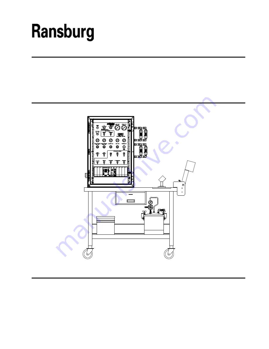
RMA-303 INDIRECT / RMA-303 DIRECT

EVOLVER 303 / EVOLVER NE

TEST STATIONS

Service Manual Price: 

  $30.00 (U.S.)

TURBINE

S.A.O./FAN

S.A.I./ATOM 

DESC

MANUFACTURER

CAT

MANUFACTURER

CAT DESC

160

160

DESC

MANUFACTURER

CAT

100

100

100

100

100

BEARING AIR

Summary of Contents for EVOLVER 303

Page 1: ...his Service Manual for future reference SERVICE MANUAL LN 9259 07 1 Replaces LN 9259 07 April 2013 RMA 303 INDIRECT RMA 303 DIRECT EVOLVER 303 EVOLVER NE TEST STATIONS Service Manual Price 30 00 U S TURBINE S A O FAN S A I ATOM DESC MANUFACTURER CAT MANUFACTURER CAT DESC 1 60 1 60 DESC MANUFACTURER CAT 100 100 100 100 100 BEARING AIR ...

Page 2: ...LN 9259 07 1 ...

Page 3: ...NTS MAINTENANCE 21 22 INTRODUCTION GENERAL INFORMATION SPECIFICATIONS FEATURES 5 8 5 5 6 7 9 20 OPERATION RMA TEST PROCEDURE INITIAL TEST SETTIN GS TESTTRIGGERS TURBINE TEST 9 9 10 11 14 15 16 16 17 17 19 WARRANTY POLICIES 23 Test Stations Contents LIMITEDWARRANTY 23 MAINTENAN 21 ...

Page 4: ...able Compare thismanualwithyoursysteminstallationdrawings and appropriate Ransburg equipment manuals to reconcile such differences Careful study and continued use of this manual will provide a better understanding of the equip ment and process resulting in more efficient operation longer trouble free service and faster easier troubleshooting If you do not have the manuals and safety literature for...

Page 5: ...r loose clothing while working around the applicator NEVERruntheapplicatorwithanyonenear the bell Serious injury COULD OCCUR if the bell is contacted while it is rotating NEVER stop the rotation of the bell by hand Use the manual air brake supplied on the test stand panel Ensure ALL items in the test area are grounded EnsurethereareNOopencontain ers of flammable materials in the test area W A R N ...

Page 6: ...Those used for general cleaning must have flash points above 100 F 37 8 C Spray booth ventilation must be kept at the rates required by NFPA33 OSHA and local codes In addition ventilation must be maintained during cleaning operations using flammable or com bustible solvents Electrostatic arcing must be prevented Test only in areas free of combustible material Testing may require high voltage to be...

Page 7: ...as of flam mable or combustible materi als may occur Personnel are exposed to high voltage during operation and maintenance Protection against inadvertent arcing that may cause a fire or explosion is lost if safety circuits are disabled during operation Frequent power supply shut down indicates a problem in the system which requires correction An electrical arc can ignite coating materials and cau...

Page 8: ...and will verify performance of single or dual fluid applicators bearing air shaping air brake air turbine drive air and fiber optic func tionality As well it checks kV and µA electrical performance of the applicator The Test Stand was developed with the user and the safety of the user in mind The user must become familiar with the overall function and operation of the unit Air Requirements 1 inch ...

Page 9: ...ANUFACTURER CAT MANUFACTURER CAT DESC TURBINE S A O FAN S A I ATOM Figure 1a Basic Station Features Test Stations Introduction 6 FEATURES 1 Main Control Panel 2 Air Flow Meters 3 Test Applicator 4 Table 5 Pressure Pot 6 Dump Bucket 7 High Voltage Cascade 8 Air Filter ...

Page 10: ...w Meter Inner Shaping Air 8 Fluid Enable Paint In Cup Wash Solvent In Cup Wash Air In 9 Atomizer Speed Select Card 10 Atomizer Card 11 MicroPak Power Supply 12 Applicator Enable Paint Trigger Cup Wash Solvent Cup Wash Air Dump 13 Regulated Function Gauges Bearing Air Outer Shaping Air Inner Shaping Air 14 High Voltage On Off Switch TURBINE S A O FAN S A I ATOM DESC MANUFACTURER CAT MANUFACTURER CA...

Page 11: ...LN 9259 07 1 Test Stations Introduction 8 NOTES ...

Page 12: ... tubing securely by hand or clamp to prevent whipping rma TEST PROCEDURE Setup 2 Provide air filtration to the manifold that has the capability of passing 30 SCFM with particulate removal of 3 to 6 micron particle size bearing air filtration is provided with the stand 3 Provide a minimum 3 4 inch ID air line to the filter at the manifold inlet A minimum of 100 psig pressure is required at the mani...

Page 13: ... 3 M10 screws 78268 00 4 Connect tubing from the Test Stand to the ap plicator as labeled 5 Supply 100 psig air pressure to the stand reference supply air gauge on panel If required adjust air input regulator attached to stand 6 Set speed select to 00 7 Adjust bearing air regulator to 90 psig mini mum 1 00 Test Stations Operation 10 ...

Page 14: ...Toggle on the Paint Trigger switch air should be escaping from the feed tube Turn off the Paint Trigger 6 Toggle Paint Fluid Enable switch to the off down position 7 Turn on the Cup Wash Air switch now turn on the Bell Solvent trigger air should be escaping from the feed tube and cup wash spout Turn off the Cup Wash Air trigger and the Cup Wash Air In switch 8 Turn on the Cup Wash Solvent switch a...

Page 15: ... off 1 00 Static Decay Water Pressure Test The purpose of this test is to verify that each of the valves in the applicator will pass fluid Also this test verifies all seals along the fluid passages have been properly installed to prevent any leakage 1 Ensure all toggle switches are set to the off or down position 2 Position the applicator where any water sprayed out of the bell may be collected an...

Page 16: ...ionized or distilled water 5 Close the lid tighten the lid clamps so that the lid is secure and no air pressure may escape 6 Turn the Fluid switch to Water position 7 Turn the Fluid Air regulator to the pressure pot to 80 psi 8 Make sure the dump line is secured in the buck et and the dump valve is in the Open position 9 Turn on Paint Fluid Enable and cup wash Solvent Fluid Enable in the Fluid Ena...

Page 17: ...tches and turn the Fluid switch to Off Shaping Air Consumption Test Inner and Outer 1 Reduce the turbine speed from 70k to 30k rpm 2 Turn on the Shaping Air dial and adjust the outer shaping air to 60 psi Reference the shaping air gauge for the correct pressure reading Ensure no air leak is present between the shaping air cap and shroud If present inspect the assembly 3 Look at the shaping air flo...

Page 18: ...freely with bear ing air supplied 4 Set the atomizer speed select to 30 000 rpm 5 Toggle Enable 1 On or in the Up position on the atomizer speed select card Then press the Speed Enter button The turbine should now begin spinning This should be audible 6 Adjust the speed select to 50 000 rpm Press the Speed Enter button to enter the new speed An audible difference in speed should be de tected Adjus...

Page 19: ...nto the HV GND port of the mounting manifold 3 Turn on the main power to the MicroPak possible causes The most likely are a Transmitter inside the bell is bad or is positioned incorrectly Refer to the RMA 303 service manual for instructions to cor rect the problem b Transmitter 75911 or cable SMC 424 XX is not properly connected or may be broken 3 On the atomizer speed select card toggle the Enabl...

Page 20: ...nel until there is 50 psi flowing on the fan air outer shaping air gauge 1 00 1 00 Air Operation 1 Connect the Test Air Cap to the spray head Toggle the Applicator Trigger switch on by placing the High Voltage Test Probe on the high voltage ring probe tips Test probe display should match the MicroPak display 6 Turn off the power supply to the MicroPak N O T E Ensure all personnel near the field ar...

Page 21: ...n Air control knob on the panel until there is 50 psi flowing on the fan air gauge Check that the fan air pressure test gauge shows a pressure 1 00 1 00 S A O FAN 4 Turn the Bell Applicator switch to OFF position N O T E Always verifty the flow meter regulator is set at 100 psi 5 Turn off the Fan and Atom Air controls 6 Remove the test cap from the applicator 2 Turn on the pressure pot valve 3 Tur...

Page 22: ...the line 7 Shut off the paint trigger 8 Turn off Pressure Pot valve Turn the Water Air switch to the Air position 9 Turn on the Applicator switch and the Dump Trigger switch until all traces of water are re moved from the dump line 10 Turn off Paint Air Enable switch to release air through the applicator 11 Turn off all switches and remove the applicator ...

Page 23: ...LN 9259 07 1 Test Stations Operation 20 NOTES ...

Page 24: ...LN 9259 07 1 Test Stations Maintenance 21 If any maintenance is required consult factory for spare part availability maintenance NOTES ...

Page 25: ...LN 9259 07 1 Test Stations Maintenance 22 NOTES ...

Page 26: ...wer supplies control units etc is one 1 year from date of purchase wrapping the applicator in plastic SHRINK WRAP ETC will void THIS war ranty RANSBURG S ONLYOBLIGATION UNDERTHIS WARRANTY IS TO REPLACE PARTS THAT HAVE FAILED BECAUSE OF FAULTY WORK MANSHIP OR MATERIALS THERE ARE NO IMPLIED WARRANTIES NOR WARRANTIES OF EITHER MERCHANTABILITY OR FITNESS FOR A PARTICULAR PURPOSE RANSBURG ASSUMES NO LI...

Page 27: ...LN 9259 07 1 ...

Page 28: ... subject to change without notice Manufacturing 1910 North Wayne Street Angola Indiana 46703 9100 Telephone 260 665 8800 Fax 260 665 8516 Technical Service Assistance Telephone 800 233 3366 Fax 419 470 2071 www ransburg com Technical Support Representative will direct you to the appropriate telephone number for ordering Spare Parts ...

Reviews: