


26
WARNING SERVICING TO BE CARRIED OUT ONLY BY AN AUTHORISED PERSON
Disconnect from electricity servicing. Check appliance is safe when you have finished.
Servicing
Disconnect from electricity supply before
commencing servicing, particularly before removing
any of the following: control panel, side panels,
ceramic hob, or any of the electrical components or
cover boxes.
Before electrical re-connection, check that the appliance
is electrically safe.
Note - References to LH and RH oven apply as viewed
from the front.
Contents
1. To Remove a Side Panel
26
2. To Lift up the Ceramic Hob
26
3. To replace a hob element.
26
4 To Remove the Control Panel
26
5. To Remove Oven Light Switch
26
6. To
Remove
Electronic
Timer
27
7. To Change Hob Controller
27
8. To
Remove
a
Thermostat
27
9 To Remove an Oven element Thermal Cut-Out.
27
10. To Remove an Oven Door
27
11. To Change Oven Door Outer Panel
27
12. To Change Oven Door Latch
27
13. To Adjust an Oven Door Catch Keep
28
14. To Change Oven Door Seal
28
15. To Remove Oven Inner Back
28
16. To Replace an Oven Fan
28
17. To Remove an Oven fan Element
28
18. To Remove the LH Oven Bottom and Top Elements
29
1. To Remove a Side Panel
Disconnect from electricity supply.
Pull the cooker forward.
Pull off the push fi t control panel end caps at each end
and remove the end fi xing screws under the end cap.
Remove the retaining screws for each panel (1 at the
front and 2 at the rear). The lower front retaining screws
(one each side) are situated beneath the lower edge at
the front corners of the side panels
Reassemble in reverse order.
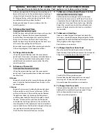
2. To Lift up the Ceramic Hob
Pull the cooker forward.
Pull off the push fi t control panel end caps at each end
and remove the end fi xing screws under the end cap.
Remove the lower front retaining screws (one each side)
situated beneath the lower edge at the front corners of
the side panels.
Swing the side panels to gain access to the hob fi xing
screws (1 each side) at the top front of the side uprights.
Remove these screws.
Caution
The ceramic hob material is much more sensitive
to scratches on the underside than the top.
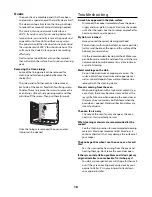
Lift up the ceramic hob at the front and prop in position
with a non-metallic prop.
Take care not to touch or scratch the underside of
the ceramic as this will weaken the material and
cause the top to shatter.
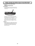
3. To replace a hob element.
Lift up the ceramic hob see 2. The elements are now
accessible.
4
To Remove the Control Panel
Disconnect from electricity supply.
Lift up the front of the ceramic hob – see 2. Remove the
control panel top scews.
Pull off all the control knobs. Open the oven doors and
remove the control panel fi xing screws underneath the
control panel. The screws directly below the clock are
for the clock fi xing bracket - don’t remove them at this
stage.
Lift the control panel, pull forward and disconnect the
wiring from the rear.
Reassemble in reverse order. When replacing leads refer
to the wiring diagram. Check operation of timer.
5. To Remove Oven Light Switch
Remove control panel (see 4).
NB The old switch may be destroyed during removal.
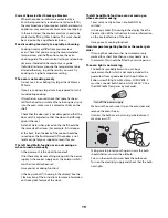
Remove switch button and old switch from its bezel by
gripping the switch body behind the control panel and
twisting sharply.
The switch bezel can then be removed by folding back
its locking wings and pushing forward. Fit the new bezel