background image

INSTALLATION

Check the appliance is electrically safe when you have finished.

29

Art No 215-0028 - Handrail fascia fixings 

ArtNo.350-0012 - Securing the plinth

ArtNo.215-0026 - Handle gaskets fixed

ArtNo.215-0027 - Elan handle blanking plugs

Final Fitting

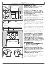
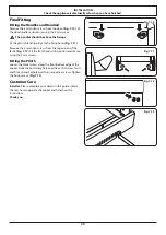
Fitting the Handles and Handrail

Remove the 4 mm Allen screws from the doors 

(Fig. 7.10)

. Fit 

the door handles and secure using the 4 mm screws.

n

n

The handles should be above the fixings.

Fit the plastic blanking plugs to the fixing holes 

(Fig. 7.11)

.

Remove the 4 mm Allen screws from the top corners of the 

fascia 

(Fig. 7.12)

. Fit the front handrail in position and secure 

using the 4 mm screws.

Fitting the Plinth

Loosen the three screws along the front bottom edge of the 

cooker. Hook the central keyhole over the central screw. Twist 

and fit each end keyhole over their respective screws. Tighten 

the fixing screws 

(Fig. 7.13)

.

Customer Care

Installer:

 Please complete your details in this guide, inform 

the user how to operate the cooker and hand over the 

instructions.

Thank you.

Fig. 7.10 

Fig. 7.11 

Fig. 7.12 

Fig. 7.13 

Summary of Contents for LECKFORD 90

Page 1: ...Britain s No 1 Range Cooker USER GUIDE INSTALLATION INSTRUCTIONS LECKFORD 90 Induction...

Page 2: ...ar and serve immediately with cream or cr me fraiche FRUITY BAKED PUDDING Serves 4 6 Ingredients 3kg 6 lb skinned and boned loin of pork 2 x 70g packs prosciutto Grated zest of 2 lemons Bay leaves Sal...

Page 3: ...17 5 Cleaning Your Cooker 18 Hob 18 Glide out Grill 19 Control Panel and Doors 19 Ovens 20 The Tall Oven 20 Cleaning Table 21 6 Troubleshooting 22 7 Installation 25 Dear Installer 25 Safety Requiremen...

Page 4: ...iv...

Page 5: ...nce results in the production of heat and moisture in the room in which it is installed Therefore make sure that the kitchen is well ventilated keep natural ventilation holes open or install a powered...

Page 6: ...uild up may make the containers burst and cause injury n n DO NOT use unstable saucepans Always make sure that you position the handles away from the edge of the hotplate Never leave the hotplate unat...

Page 7: ...uld a crack appear in the surface disconnect the appliance immediately from the supply and arrange for its repair Always LIFT pans off the hob Sliding pans may cause marks and scratches Fig 1 4 Always...

Page 8: ...n hob The kind of pan you use and the quantity of food affects the setting required Higher settings are required for larger quantities of food Pots and pans should have thick smooth flat bottoms Fig 2...

Page 9: ...ng induction hob functions Pan detector H Residual heat indicator A Automatic heat up Child lock L1 L2 Low temperature setting P Power boost setting Pan Detector IMPORTANT After use switch off the hob...

Page 10: ...he 0 power setting or turning the control knob to the 9 power setting For your guidance Table 2 2 shows the time available at 100 power depending on the power level selected in the Automatic Heat up m...

Page 11: ...y n n This is a built in safety device Deactivate the Power Boost function by turning the control knob to a lower setting Overheat Function This function identifies when the temperature of the pan ris...

Page 12: ...and the food placed on it while you are waiting for the grill to preheat n n DO NOT leave the grill on for more than a few moments without the grill pan underneath it otherwise the knobs may become ho...

Page 13: ...ld be used to complete most of your cooking The browning element and base heat can be used in the latter part of the cooking process to fine tune the results to your particular requirements Use fanned...

Page 14: ...top and base elements It is particularly suitable for roasting and baking pastry cakes and biscuits Food cooked on the top shelf will brown and crisp faster than on the lower shelf because the heat i...

Page 15: ...ith high water content there may be some steam visible at the grille at the rear of the hotplate This is perfectly normal Fan Ovens Turn the oven knob to the desired temperature Fig 2 15 The oven indi...

Page 16: ...e g 20 seconds Fig 2 19 3 Turn the Timer A knob to the Manual D setting to see the current time and the Bell symbol on the display Fig 2 20 Cancel the Timer Alarm Once the specified time has elapsed...

Page 17: ...it an alarm There are two ways to cancel the alarm refer to Cancel the Timer Alarm on page 12 To Start and Stop the Multifunction Oven The Multifunction Oven allows you to automatically start and stop...

Page 18: ...ivate the left hand oven 1 Cancel any active programs Refer to Reset to Manual Cooking on page 14 2 Turn the Timer A knob to the Clock C setting and hold for approx 8 seconds The display will show ON...

Page 19: ...fits to the left hand oven door only Food cooking on it is easy to attend to because it is accessible when the door is open The maximum weight that can be held by the Handyrack is 5 5kg 12lb It should...

Page 20: ...eather n n DO NOT place warm food in the oven to be timed n n DO NOT use a timed oven that is already warm n n DO NOT use the timed oven if the adjoining oven is already warm Whole poultry must be tho...

Page 21: ...0 minutes according to size 2 3 hours 45 60 minutes 40 45 minutes 2 to 3 hours 20 30 minutes 15 20 minutes 15 20 minutes per 500g Steaks according to thickness Conventional Oven Temperature C Shelf Po...

Page 22: ...ll other than a sugary substance is on the hot zone do not clean until the unit has completely cooled down and then follow the instructions below Cleaning Burned on Spills If you accidentally melt any...

Page 23: ...ig 5 3 For each side support the side rail with one hand and with the other hand lift the frame up and out of the side clips Fig 5 4 For safety push the side rails back into the grill chamber If you n...

Page 24: ...elf supports Remove the oven shelves Pull the top of the shelf support away from the oven side and lift the support away from the locating bracket at the bottom of the oven side Fig 5 7 Refit in the r...

Page 25: ...y water soft cloth Splashback rear grille Enamel or stainless steel Hot soapy water soft cloth Cream cleaner with care if necessary Control panel Paint enamel stainless steel glass Warm soapy water Do...

Page 26: ...h power settings or if 5 pans are used simultaneously The type of pan may also contribute to induction noise The cooling fan The induction hob incorporates a cooling fan This cooling fan is active whe...

Page 27: ...4 Retighten the hinge screws Note The tall oven door cannot be adjusted The oven is not cooking evenly Do not use a baking tray with dimensions larger than those specified in the section on General Ov...

Page 28: ...he oven is locked See the Clock section of the instructions for more information on the key lock feature The timed oven is not coming on when automatic cooking Has the oven knob been left in the OFF p...

Page 29: ...ments n n The appliance must be installed in accordance with the regulations in force and only in a well ventilated space n n Read the instructions before installing or using this appliance Provision...

Page 30: ...ash and steam resistant Certain types of vinyl or laminate kitchen furniture are particularly prone to heat damage and discolouration We cannot accept responsibility for damage caused by normal use of...

Page 31: ...wing Connection If you need to move the cooker once it has been connected make sure it is switched off at the supply switch before gripping under the fascia panel and lifting the front of the cooker s...

Page 32: ...BE EARTHED Note The cooker must be connected to the correct electrical supply as stated on the voltage label on the cooker through a suitable cooker control unit incorporating a double pole switch ha...

Page 33: ...fixings Fit the plastic blanking plugs to the fixing holes Fig 7 11 Remove the 4mm Allen screws from the top corners of the fascia Fig 7 12 Fit the front handrail in position and secure using the 4mm...

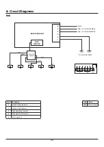
Page 34: ...1 2 5 3 4 INDUCTION UNIT HOB DISPLAY Earth N 6 N 4 L 2 L 3 On Terminal Block On Terminal Block On Terminal Block w br w br w br w br w br Code Description 1 Left hand front element 2 Left hand back el...

Page 35: ...3 B8 D4 F1 G H G H F2 G H I A1 Code Description A1 Grill front switch A2 Grill energy regulator A3 Grill elements B1 Left hand oven front switch B2 Left hand oven thermostat B3 Left hand oven top elem...

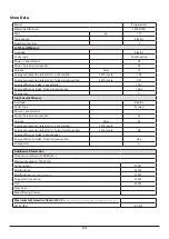
Page 36: ...ker Ratings Max 1 85 kW Boost 2 5 kW Max 1 85 kW Boost 3 0 kW Max 1 85 kW Boost 2 5 kW Max 1 15 kW Boost 2 0 kW Max 1 15 kW Boost 2 0 kW Zone 1 Zone 2 Zone 3 Zone 5 Zone 4 Hotplate energy saving tips...

Page 37: ...ergy Consumption ECElectric cooking Wh kg 172 Zone 3 cm 18 5 Heating Technology Energy Consumption ECElectric cooking Wh kg 180 Zone 4 cm 15 5 Heating Technology Energy Consumption ECElectric cooking...

Page 38: ...hand Efficiency Fuel type Electric Cavity type Fanned Power conventional Power forced air convection 2 5 Volume Litres 67 Energy consumption electricity conventional kWh cycle Energy consumption elec...

Page 39: ...authorised to act on behalf of AGA Rangemaster Exceptions Items not included under the free 1 year warranty include pan supports griddles wok rings baking trays grill pans trivets filters light bulbs...

Page 40: ...ed Office Juno Drive Leamington Spa Warwickshire CV31 3RG Search Rangemaster UK Rangemaster continuously seeks improvements in specification design and production of products and thus alterations take...

Reviews: