Command reference
R&S
®
ZNB/ZNBT
927
User Manual 1173.9163.02 ─ 62
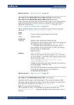
CALCulate<Chn>:LIMit:DATA
<Type>, <StartStim>, <StopStim>, <StartResp>,
<StopResp>
Defines the limit line type, the stimulus and response values for a limit line with an arbi-
trary number of limit line segments. See
Chapter 4.4.1.1, "Rules for limit line definition"
Note:
CALCulate<Chn>:LIMit:CONTrol[:DATA]
does not overwrite existing limit line segments. The defined segments are appended to
the segment list as new segments.
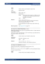
Suffix:
<Chn>
.
Channel number used to identify the active trace
Parameters:
<Type>
Identifier for the type of the limit line segment:
0
–
limit line segment off, segment defined but no limit check
performed.
1
–
upper limit line segment
2
–
lower limit line segment
Range:
0, 1, 2 (see above)
<StartStim>,
<StopStim>,
<StartResp>,
<StopResp>
Stimulus and response values of the first and last points of the
limit line segment.
The unit of the stimulus values is adjusted to the sweep type of
the active channel (
), the unit of
the ripple limit is adjusted to the format of the active trace
(
Example:
*RST; :CALC:LIM:CONT 1 GHZ, 1.5 GHZ
Define an upper limit line segment in the stimulus range
between 1 GHz and 1.5 GHz, using default response values.
CALC:LIM:DATA 1, 1500000000, 2000000000, 2, 3
Define an upper limit line segment in the stimulus range
between 1.5 GHz and 2 GHz, assigning response values of +2
dB and +3 dB.
CALC:LIM:DISP ON
Show the limit line segment in the active diagram.
Manual operation:
See
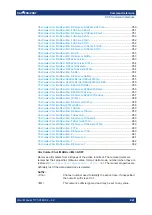
CALCulate<Chn>:LIMit:DCIRcle:CLEar
Resets the display circle to its default configuration (unit circle; show border: off; limit to
circle: off).
Suffix:
<Chn>
.
Channel number used to identify the active trace
Usage:
Event
Manual operation:
See
SCPI command reference

