background image

Connecting the probe

R&S

®

RT

ZM

22

User Manual 1419.3128.02 ─ 05

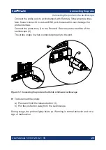
To connect the probe tips to the probe amplifier

1. Connect the probe to an oscilloscope channel to ensure that the amplifier is

grounded.

2. Push the tip module straight in the probe amplifier to connect them.

To disconnect the probe tips from the probe amplifier

NOTICE! 

Risk of damaging the device. Do not bend the probe tip module to

pop it loose from the amplifier. Do not wiggle the probe tip module up and
down or twist it to remove the connector from the probe amplifier.
Pull the tip module connectors straight out of the sockets.

3.4.2


Considerations for soldering

For best measurement results and to avoid damaging the probe, observe the fol-
lowing when soldering in the probe tips:

Always disconnect the probe tip module from the probe amplifier before unsol-
dering or disconnecting it, moving it to a new position and resoldering or
reconnecting it.

Do not leave the soldering iron in contact with the probe tip for more than a
few seconds at a time. Excess heat can damage the probe.

Some solder-in accessories are very fine and sensitive. Stabilize the probe
using appropriate means (e.g. adhesive pads, probe positioner) to protect the
solder joint from excessive mechanical stress.

Always keep soldered leads as short as possible for best performance and
signal integrity.

3.4.3


R&S


RT

ZMA10 tip cable solder-in

The R&S


RT

ZMA10 tip cable solder-in is a semi-permanent solder-in connection

that supports the full bandwidth of the probe amplifier. It is well suited for creating
solid contact with test points that are hard to reach (e.g. IC pins).

Connecting the probe to the DUT

Summary of Contents for RT-ZM

Page 1: ...R S RT ZM Modular Probe System User Manual 1419312802 Version 05 COL2...

Page 2: ...9 0 Email info rohde schwarz com Internet www rohde schwarz com Subject to change data without tolerance limits is not binding R S is a registered trademark of Rohde Schwarz GmbH Co KG Trade names are...

Page 3: ...f the probe 12 2 4 Accessories and items 14 3 Connecting the probe 19 3 1 Handling the probe 19 3 2 Connecting the probe to the oscilloscope 19 3 3 Identification of the probe 21 3 4 Connecting the pr...

Page 4: ...Contents R S RT ZM 4 User Manual 1419 3128 02 05 5 3 Returning for servicing 47 5 4 Calibration interval 47 5 5 Storage and transport 48 5 6 Disposal 48 5 7 Spare parts 48...

Page 5: ...sted in the pro be s data sheet Where do I find safety information Safety information is part of the product documentation It warns you of potential dangers and gives instructions on how to prevent pe...

Page 6: ...doors The product casing is not waterproof Water that enters can electrically connect the casing with live parts which can lead to elec tric shock serious personal injury or death if you touch the cas...

Page 7: ...Otherwise the measurement results do not reflect the actual volt age level and you might misjudge the actual risk The probe pins are extremely pointed and can easily penetrate clothes and the skin Ha...

Page 8: ...y of the safety hazard and how likely it will occur if you do not follow the safety precautions WARNING Potentially hazardous situation Could result in death or serious injury if not avoi ded CAUTION...

Page 9: ...eet tomorrow s challenges in probing The probe is equipped with the Rohde Schwarz probe interface It can be con nected to any Rohde Schwarz instrument that is compatible with this interface When conne...

Page 10: ...The function is assigned at the oscilloscope For details see Chapter 4 4 Micro button on page 41 R S ProbeMeter The R S ProbeMeter measures the DC voltage of the input signal directly at the probe ti...

Page 11: ...easurement accuracy 2 2 Unpacking and checking 1 Unpack the product carefully 2 Retain the original packing material Use it when transporting or shipping the product later 3 Using the delivery notes c...

Page 12: ...The probe consists of the active probe amplifier the probe box for connection to the oscilloscope the probe cable and various probe tip modules Figure 2 1 R S RT ZM probe consisting of probe amplifier...

Page 13: ...e required supply voltage and is also used to transmit analog signals and digital data simultaneously All the analog voltages required by the probe are gen erated in the probe box The BNC connector is...

Page 14: ...Chapter 3 4 Connecting the probe to the DUT on page 21 If you need more probe tip modules you can order them at Rohde Schwarz The order numbers are provided in the data sheet Figure 2 2 R S RT ZM pro...

Page 15: ...Manual 1419 3128 02 05 Table 2 1 Accessories supplied Item Quantity Description 1 Lead 15 cm 5 9 in 1 Solder wire 0 1mm Ag plated 10 m 1 Solder wire 0 2mm Ag plated 10 m 1 Solder wire lead free 5 m 7...

Page 16: ...ge 48 2 4 2 Optional accessories If the delivered accessories do not meet individual customer requirements Rohde Schwarz offers different accessory sets for sale The order numbers are provided in the...

Page 17: ...R S probe interface to the following standard connectors USB C for power and control SMA for signal and DC jack for auxiliary supply Together with the R S RT ZA51 probe to 3 5 mm adapter it moves the...

Page 18: ...the probe to do perfor mance tests and for servicing The service kit includes all adapters and accessories to connect the probe to the required measuring instruments R S RT ZM Service Manual The servi...

Page 19: ...atic discharge can damage the electronic components of the product and the device under test DUT Ground yourself to prevent electrostatic discharge damage a Use a wrist strap and cord to connect yours...

Page 20: ...box 1 to the Rohde Schwarz probe interface of the oscilloscope 2 The probe snaps in when connected properly to the port Figure 3 1 Connecting the probe to the Rohde Schwarz oscilloscope To disconnect...

Page 21: ...uations to measure with confidence in the perfor mance and signal fidelity Using the recommended connection configurations is your key to making accurate oscilloscope measurements with known perfor ma...

Page 22: ...soldering in the probe tips Always disconnect the probe tip module from the probe amplifier before unsol dering or disconnecting it moving it to a new position and resoldering or reconnecting it Do n...

Page 23: ...guration you can measure single ended differential and common mode signals without resoldering the tip cable 1 Solder both signal leads P N in front of the tip board and to the DUT 2 Solder both groun...

Page 24: ...g onto pin strips with a pitch of 1 27 mm 50 mil Bandwidth up to 6 GHz MultiMode compatible Length 15 cm Distance range 1 27 mm 50 mil Temperature range 30 C to 80 C Measurements with MultiMode In thi...

Page 25: ...reconnect different test points using the clamp connector of the tip cable Bandwidth up to 16 GHz MultiMode compatible Length 15 cm Variable span range of the leads 0 mm to 5 mm 0 mil to 200 mil Temp...

Page 26: ...4 Use the clamp connector to connect and reconnect the RT ZMA14 tip cable 3 4 6 R S RT ZMA15 tip cable quick connect The R S RT ZMA15 tip cable quick connect makes it easy to plug and remove connecti...

Page 27: ...two resistors to the DUT 3 Connect and reconnect the socket head to the measurement point Measurements in DM mode In this configuration you can measure only differential signals 1 Permanently solder t...

Page 28: ...AUTION The browser module pins are very sharp handle them carefully Insert the pins in the browser module if needed 2 NOTICE Applying a side load to the browser module can damage the brows er s pins D...

Page 29: ...e compatible Termination voltage range 4V with a maxi mum current of 40 mA Distance range up to 65 mm 2560 mil Connecting to the DUT 1 To connect the SMA module to the output sockets of the DUT use th...

Page 30: ...ing from the DUT 1 Remove the SMA module from the DUT 2 Disconnect the probe amplifier from the oscilloscope 3 4 9 R S RT ZMA50 extreme temperature kit The R S RT ZMA50 extreme temperature kit contain...

Page 31: ...ge from 0 C to 40 C Connect the R S RT ZMA11 tip cable solder in ET to the 1 m extension cable pair 2 Connect the other end of the extension cable pair to the R S RT ZM probe amplifier Measurements in...

Page 32: ...lder both ground wires GND at the outside of the tip board and to the DUT Measurements in DM mode In this configuration you can measure only differential measurements 1 Solder both signal leads P N to...

Page 33: ...different input voltages can be measured with the MultiMode feature P Mode pos Single ended input voltage Vp Voltage between the positive input terminal and ground N Mode neg Single ended input volta...

Page 34: ...nd ground Figure 4 2 Displayed voltage on oscilloscope screen The setting of the probe mode is part of the probe settings of the channel to which the probe is connected You can also configure the micr...

Page 35: ...w each pin to ground 7 0 VDC to 100 kHz 5 0 V 100 kHz at 10 1 attenuation 1 0 V 100 kHz at 2 1 attenuation The dynamic range for differential measurement DM Mode designates the maximum differential vo...

Page 36: ...even in front of the active probe amplifier is possible with an extremely wide compensa tion range of 16 V The offset compensation feature is available for every MultiMode setting MultiMode setting O...

Page 37: ...micro button to compensate the DC component of the measurement signal which is helpful during measurements of input signals with different DC offsets Therefore assign Set offset to mean to the micro...

Page 38: ...ted to ground using an R S RT ZM15 30 60 90 130 160 4 3 2 Common mode offset The common mode offset function can compensate a DC voltage applied to both input terminals at the probe tip referenced to...

Page 39: ...mpensate a DC voltage applied to the positive input terminal Vp at the probe tip referenced to ground Setting a P offset compensa tion in single ended P measurement mode is directly visible on the osc...

Page 40: ...gative input terminal Vn at the probe tip referenced to ground Setting an N offset compen sation in single ended N measurement mode is directly visible on the oscilloscope screen as a voltage offset o...

Page 41: ...f the oscilloscope High precision measurements are achieved by immediate digitization of the mea sured DC voltage at the probe tip The R S ProbeMeter measures the differential and common mode DC volta...

Page 42: ...he input signal loading caused by a probe tip module is determined by its input impedance The following plots show the single ended and differential input impe dance of various RT ZMA tip modules The...

Page 43: ...Features and characteristics of modular probes R S RT ZM 43 User Manual 1419 3128 02 05 Figure 4 8 Input impedance R S RT ZMA10 Figure 4 9 Input impedance R S RT ZMA12 Input impedance...

Page 44: ...Features and characteristics of modular probes R S RT ZM 44 User Manual 1419 3128 02 05 Figure 4 10 Input impedance R S RT ZMA14 Figure 4 11 Input impedance R S RT ZMA15 Input impedance...

Page 45: ...ures and characteristics of modular probes R S RT ZM 45 User Manual 1419 3128 02 05 Figure 4 12 Input impedance R S RT ZMA30 Figure 4 13 Input impedance R S RT ZMA50 with R S RT ZMA11 tip Input impeda...

Page 46: ...alcohol Keep in mind that the casing is not waterproof Note Do not use cleaning agents Solvents thinners acetone acids and bases can damage the labeling or plastic parts 2 Dry the product completely...

Page 47: ...er the following 1 Use a sufficiently sized box 2 Protect the product from damage and moisture e g with bubble wrap 3 Use some kind of protective material e g crumpled newspaper to stabilize the produ...

Page 48: ...that causes minimum environmental impact Disposing electrical and electronic equipment A product that is labeled as follows cannot be disposed of in normal household waste after it has come to the en...

Page 49: ...Pos Item Description Material number 1 Adhesive pads 1800 4268 00 2 Cable marker 1800 4245 00 3 Lead wire black ground 1800 4222 00 4 Solder wire 0 2mm Ag plated 1800 4074 00 5 Solder wire 0 1mm Ag pl...

Page 50: ...al tool 1800 4451 00 11 Pogo pin Pogo pin connector 6 pins 3584 6396 00 12 R S RT ZK3 R S RT ZK3 service kit 1419 3934 02 Table 5 2 Accessories for R S RT ZMA14 Pos Item Description Material number 1...

Page 51: ...sories for R S RT ZMA40 Pos Item Description Material number 1 Semi rigid cable 1419 4276 00 2 Lead wire red termination voltage 1800 4239 00 Table 5 5 Parts for ESD prevention Pos Item Material numbe...

Reviews: