background image

R&S OSP 

Instrument Functions 


Operating Manual 1505.3896.12 - 14 

76 

5.1.1  R&S OSP Block Diagram 

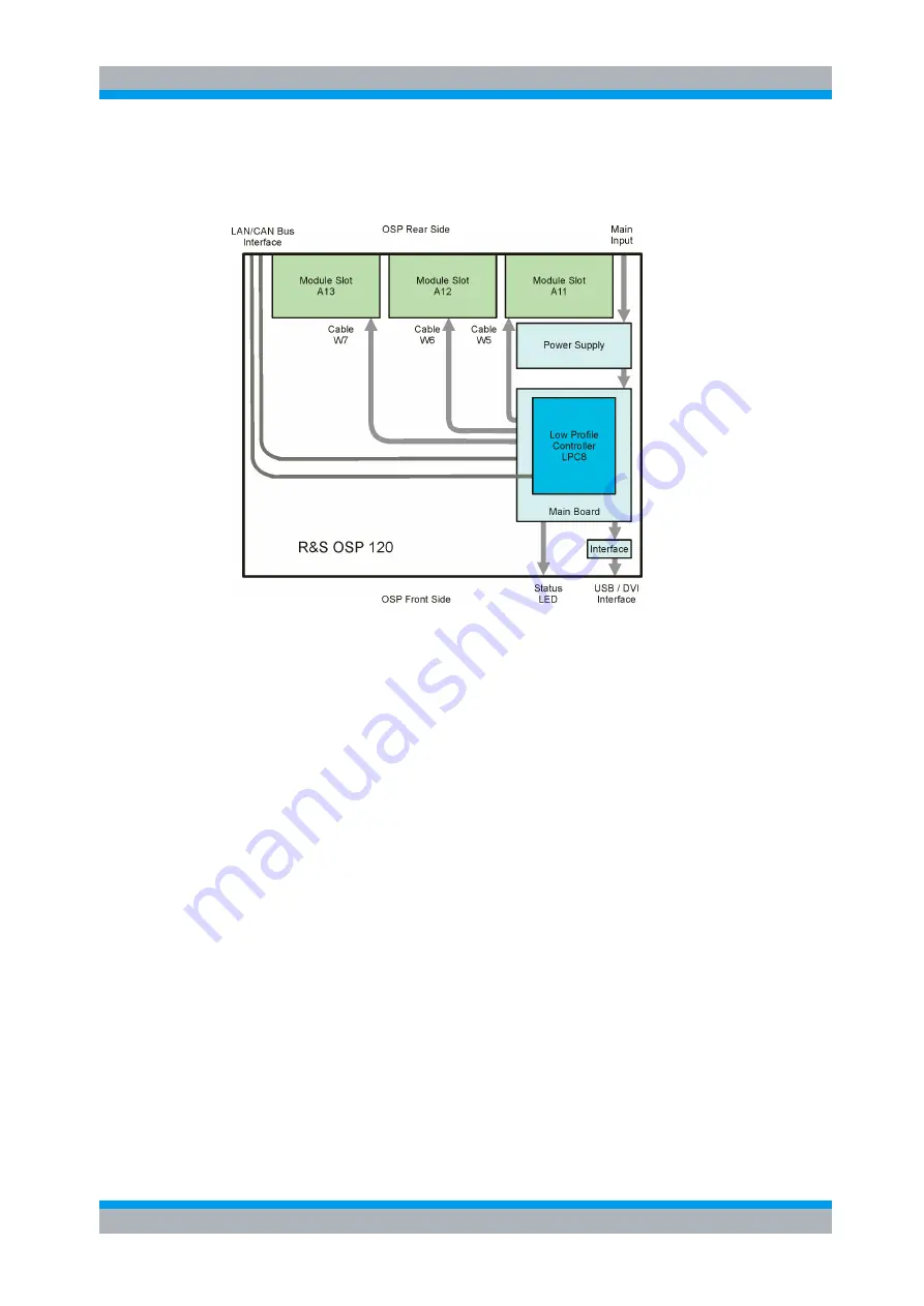
The following block diagram shows the main functional groups of the R&S OSP120. 


Figure 5-1: Block Diagram R&S OSP120 

The central part of the R&S OSP frame is the Low Profile Controller LPC8 with Linux 
Operating System. The computer handles the external interfaces of the R&S OSP120 
such as LAN, USB and DVI. It also serves the internal interfaces in the R&S OSP120 
like the control ports for the three slots which can take the R&S OSP modules.  

The single board computer is plugged onto the R&S OSP Main Board. The basic 
component on the mainboard is an FPGA which supplies all necessary interfaces 
between computer PCI Bus and R&S OSP internal interfaces like the control ports for 
the R&S OSP modules. The CAN bus which is used to connect further R&S OSP 
extension units is implemented in the FPGA as well. 

The power is supplied by a 175 W switching type power supply. The supply voltage for 
the R&S OSP modules and their relays is generated by a voltage converter which is 
placed on the Main Board.  

Via a small interface board the connectors of the Low Profile Controller are adapted to 
the standard interfaces to connect USB devices and the DVI monitor. 

Summary of Contents for OSP

Page 1: ...PAD T M 3574 3259 02 01 00 CI 1 EN R S OSP Open Switch and Control Unit Operating Manual Operating Manual Test and Measurement 1505 3896 12 14...

Page 2: ...n Module R S OSP B124 stock no 1515 5533 02 Option Module R S OSP B125 stock no 1515 5540 02 Option Module R S OSP B126 stock no 1515 5556 02 Option Module R S OSP B127 stock no 1505 4728 02 Option Mo...

Page 3: ...e of the product The product is used for its designated purpose if it is used in accordance with its product documentation and within its performance limits see data sheet documentation the following...

Page 4: ...ation item 7 Signal words and their meaning The following signal words are used in the product documentation in order to warn the reader about risks and dangers Indicates a hazardous situation which i...

Page 5: ...afety is not observed either at all or to the extent necessary electric shock fire and or serious personal injury or death may occur 1 Prior to switching on the product always ensure that the nominal...

Page 6: ...t be fuse protected in such a way that anyone who has access to the product as well as the product itself is adequately protected from injury or damage 14 Use suitable overvoltage protection to ensure...

Page 7: ...masks and protective clothing must be worn 7 Laser products are given warning labels that are standardized according to their laser class Lasers can cause biological harm due to the properties of the...

Page 8: ...n permitted 5 If a cell develops a leak the fluid must not be allowed to come into contact with the skin or eyes If contact occurs wash the affected area with plenty of water and seek medical aid 6 Im...

Page 9: ...s substances or fuels can cause health problems and lead to environmental damage For additional information about environmental protection visit the Rohde Schwarz website Instrucciones de seguridad el...

Page 10: ...el uso del producto Deber n tenerse en cuenta todas las dem s informaciones de seguridad como p ej las referentes a la protecci n de personas que encontrar n en el cap tulo correspondiente de la docu...

Page 11: ...l producto se emplea de forma sin nima el t rmino CUIDADO Las palabras de se al corresponden a la definici n habitual para aplicaciones civiles en el rea econ mica europea Pueden existir definiciones...

Page 12: ...la tensi n preseleccionada en el producto coincida con la de la red de alimentaci n el ctrica Si es necesario modificar el ajuste de tensi n tambi n se deber n cambiar en caso dado los fusibles corre...

Page 13: ...efectuadas por un electricista especializado 13 En el caso de dispositivos fijos que no est n provistos de fusibles interruptor autom tico ni otros mecanismos de seguridad similares el circuito de ali...

Page 14: ...presario operador tiene la obligaci n de evaluar y se alizar las reas de trabajo en las que exista un riesgo elevado de exposici n a radiaciones 6 Tenga en cuenta que en caso de incendio pueden despre...

Page 15: ...r ni fuego Debe evitarse el almacenamiento a la luz directa del sol Las celdas y bater as deben mantenerse limpias y secas Limpiar las conexiones sucias con un pa o seco y limpio 3 Las celdas o bater...

Page 16: ...vos el ctricos usados no se deben desechar con los residuos dom sticos sin clasificar sino que deben ser recogidos por separado Rohde Schwarz GmbH Co KG ha elaborado un concepto de eliminaci n de resi...

Page 17: ...ument up to date and to be informed about new application notes related to your instrument please send an e mail to the Customer Support Center stating your instrument and your wish We will take care...

Page 18: ...Switch and Connector 19 2 5 Putting the Instrument into Operation 20 2 5 1 Unpacking the Instrument and Checking the Shipment 20 2 5 2 Instrument Setup 21 2 5 3 Bench Top Operation 21 2 5 4 Mounting i...

Page 19: ...eral Actions of R S OSP Panel 42 3 3 5 Addressing R S OSP Modules 43 3 3 6 Controlling the R S OSP B101 B106 B107 B111 B127 B132 44 3 3 7 Controlling the R S OSP B102 B112 B128 45 3 3 8 Controlling th...

Page 20: ...3 5 2 2 RF Switch Module R S OSP B102 B112 B128 84 5 2 3 I O Module R S OSP B103 86 5 2 4 I O Module R S OSP B104 88 5 2 5 RF Switch Module R S OSP B106 B132 90 5 2 6 DC MUX Module R S OSP B108 91 5 2...

Page 21: ...9 5 7 SCPI Read Write 130 5 7 1 R S OSP Temperature Read Command 131 6 Remote Control 133 6 1 Remote Control Operation 133 6 1 1 Establishing and Testing a LAN Connection 134 6 1 2 Switchover to Remot...

Page 22: ...ith R S EMC32 176 8 2 R S OSP Drivers 179 8 3 Extending the R S OSP System 180 8 3 1 R S OSP150 Extension Unit 180 8 3 2 Connecting the R S OSP150 181 8 3 3 How to Register the R S OSP150 182 8 4 Appl...

Page 23: ...9 2 5 R S OSP B108 Interface 203 9 2 6 R S OSP B106 Interface 204 9 2 7 R S OSP B121 Interface 204 9 2 8 R S OSP B122 Interface 205 9 2 9 R S OSP B123 Interface 205 9 2 10 R S OSP B124 Interface 206...

Page 24: ...S OSP B128 86 Figure 5 17 Module R S OSP B103 87 Figure 5 18 Block Diagram Module R S OSP B103 87 Figure 5 19 Module R S OSP B104 88 Figure 5 20 Block Diagram Module R S OSP B104 89 Figure 5 21 Modul...

Page 25: ...9 7 Pin Assignment R S OSP B103 Input 201 Figure 9 8 Pin Assignment R S OSP B103 Output 201 Figure 9 9 Pin Assignment R S OSP B104 Relay Control 202 Figure 9 10 Pin Assignment R S OSP B104 Input Outpu...

Page 26: ...o 1505 5718 02 Option Module R S OSP B111 stock no 1505 4605 02 Option Module R S OSP B112 stock no 1505 4611 02 Option Module R S OSP B114 stock no 1505 4711 02 Option Module R S OSP B116 stock no 15...

Page 27: ......

Page 28: ...he beginning of this manual 2 1 Front Panel Tour R S OSP120 This chapter gives an overview of the front panel controls and connectors of the R S OSP120 and gives all information that is necessary to p...

Page 29: ...CAN bus On an R S OSP150 the logic is inverted the CLK indicator goes off shortly during CAN bus activity The STANDBY key serves the following purpose Toggle between standby and ready state indicated...

Page 30: ...equired It is recommended to use a double shielded monitor cable equipped with ferrites at each end 2 2 Front Panel Tour R S OSP130 This chapter gives an overview of the front panel controls and conne...

Page 31: ...In the top row next to the screen there are three keys to quickly access different hierarchy levels in the menus pressing the key FUNCTION executes a switching action if applicable pressing the key O...

Page 32: ...se double shielded USB cables 2 3 Front Panel Tour R S OSP150 This chapter gives an overview of the front panel controls of the R S OSP150 The front panel of the R S OSP150 is similar to the front pan...

Page 33: ...nsisting of two coaxial relays of SP6T type the RF coaxial connectors are SMA type Option R S OSP B103 I O module with 16 Bit input output ports the connectors are D Sub types 25 pin female for output...

Page 34: ...tion of the fiber optic extender R S OSP Z104 Using the cable OSP Z106 is recommended for this case However when connecting an R S OSP150 to an OSP120 or OSP130 this supply voltage line must not be pr...

Page 35: ...Checking the Shipment Remove the instrument from its packaging and check the equipment for completeness using the delivery note and the accessory lists for the various items First pull off the polyet...

Page 36: ...Bench Top Operation If the R S OSP is operated on a bench top the surface should be flat The instrument is used in horizontal position standing on its feet 2 5 4 Mounting in a 19 Rack The instrument...

Page 37: ...he power on or off press the AC power switch to position I On or 0 Off See also Replacing Fuses After power on the R S OSP instrument is in ready state after about 30 seconds The STANDBY key at the fr...

Page 38: ...anging from Standby to Ready state the left PWR LED is immediately switched to green and all modules are power supplied Please note that the Linux operating system of R S OSP takes about 30 seconds to...

Page 39: ...the R S OSP120 provides interfaces for monitor connection and USB connection An external monitor shows the menus of the Linux Operating System if any access or setup within the Linux Operating System...

Page 40: ...OSP120 or OSP130 To establish a LAN connection proceed as follows Refer to chapter Assigning an IP Address and learn how to avoid connection errors Connect an appropriate LAN cable to the LAN port Use...

Page 41: ...e STANDBY key which will shut down the Linux operating system and set the instrument to standby state If desired set the AC power switch to position 0 Off Standby state It is recommended to switch the...

Page 42: ...n to the LAN without any previous R S OSP configuration Priority 1 A user defined static IP address This address can be defined but must not in addition to the default address See chapter 3 3 3 for in...

Page 43: ...key on the keyboard OK key for the R S OSP130 for confirmation and to continue the operation Manual TCP IP configuration If your network does not support DHCP proceed as follows 1 Connect the R S OSP...

Page 44: ...all R S OSP functions To start the OSP Panel connection 4 Connect the R S OSP to a LAN and determine its IP address see Remote Operation in a LAN It is necessary to have a VISA library installed on yo...

Page 45: ...d keyboard to the R S OSP120 and switch on the instrument The messages of the Linux boot process are displayed on the monitor Wait until the boot process is finished takes about 30 seconds and press t...

Page 46: ...ns are provided on the Internet at the download site of the R S OSP homepage The installation of a new firmware version is performed via the USB interface A de installation of the old firmware is not...

Page 47: ...Update The firmware update is not allowed to be performed running the GUI via Web Browser and VNC Doing this will abort the firmware installation procedure 2 12 Read the actual the Firmware Version T...

Page 48: ...xample The last part of the string shows the actual firmware version 1 5 for the above example With Firmware version 2 51 onwards the actual version of the OSP is read out in the configuration string...

Page 49: ...panel keypad GUI Figure 3 2 Chapter 4 and Chapter 5 3 1 R S OSP120 and R S OSP130 via Ethernet connection between OSP and laptop PC Web GUI via VNC or OSP Panel Figure 3 3 Chapters 3 1 3 7 1 5 3 1 Web...

Page 50: ...ssume that you are familiar with standard Windows dialogs and mouse operation 3 1 Connecting R S OSP and PC Please read chapter 2 9 1 for understanding the possibilities of IP address assignments The...

Page 51: ...lication proceed as follows Insert the documentation CD on the disk drive of your computer Select the directory OSP Panel on the CD select the file setup exe and press the ENTER button to start the in...

Page 52: ...the following dialog appears The R S OSP remains in simulation mode as long as no connection to an instrument via LAN is performed To connect an R S OSP via LAN perform the following steps 1 Get the a...

Page 53: ...ogether with the installed options Note that it is necessary to register the R S OSP once if the instrument is switched on for the first time or if the configuration has changed or if a firmware updat...

Page 54: ...xxxK03 Serial Number 100001 The above example results in R S OSP address 3100001 OSP Description Base unit OSP120 OSP130 or Extension unit OSP150 Mainboard Serial Number The serial number read back fr...

Page 55: ...version last digit of the OSP part number and the OSP serial number 6 digit number The information of the OSP version and the serial number can be found on the serial number label above the mains swi...

Page 56: ...more information on the LAN configuration mode Select the menu function Configure TCPIP and the following dialog is opened The upper half of the dialog shows the last used DHCP address and the actual...

Page 57: ...be done from the OSP Panel With the menu function Configure Reset all switches in the connected R S OSP are set to their default positions The functions Configure Select all Switches and Configure Des...

Page 58: ...ld of the OSP Panel dialog By double clicking the required R S OSP module a window is opened which shows all the setup functions available for the selected module The title line of that window also in...

Page 59: ...When the relay is not activated terminal NC is connected to terminal C The terminal NO is the Normally Open position If the relay is activated the terminal NO is connected to terminal C The buttons K...

Page 60: ...a similar relay configuration It will apply to the following modules Option Relay configuration OSP B106 3 x SPDT relay with N connectors 12 GHz 3 x SPDT relays with BNC connectors 900 MHz 2 A OSP B1...

Page 61: ...the switches but for defining a path configuration see chapter 3 4 K1 A button K1 and or K2 in grey color indicates that this relay is not selected A non selected relay is not considered when defining...

Page 62: ...S OSP as far as the option has got the same relay configuration It will apply to the following modules Option Relay configuration OSP B112 2 x SP6T relay 40 GHz OSP B128 Up 3 x SP6T relay solid state...

Page 63: ...to the defined output pattern 6 The actual setting of the R S OSP B103 outputs now is displayed in the output pattern field Ch1 to Ch16 7 The hexadecimal representation of the output pattern is displ...

Page 64: ...pted to close the actual panel and to open it again After opening the OSP B158 panel again a special interface for controlling the AU600 antenna system appears Figure 3 4 AU600 panel design AU600 pane...

Page 65: ...tors 1 and 4 and between 2 and 3 The buttons R1 up to R4 are not required for manual operation of the switches but for defining a path configuration see chapter 3 4 R1 Any button R1 up to R4 in grey c...

Page 66: ...lay data specification If the delay time is too short the relay status also may be shown as faulty See chapter 5 2 4 for further information on the relay delay time 3 3 9 2 Setting the Output Pattern...

Page 67: ...t pattern field Ch1 to Ch4 The hexadecimal representation of the input pattern is displayed in the OSP B104 dialog too Ch1 corresponds to the lowest bit having the value 1 whereas Ch4 is the highest b...

Page 68: ...on of the switches but for defining a path configuration see chapter 3 4 K1 A button K1 and or K2 in grey color indicates that this relay is not selected A non selected relay is not considered when de...

Page 69: ...Any button K11 and or K12 in grey color indicates that this relay is not selected A non selected relay is not considered when defining a path configuration K11 To take over particular relays into the...

Page 70: ...see chapter 3 4 K12 Any button K11 and or K12 in grey color indicates that this relay is not selected A non selected relay is not considered when defining a path configuration K11 To take over particu...

Page 71: ...y buttons The selected relay is displayed with a button in green color All relays whose relay buttons are selected are taken over into a path configuration Pressing the Shift key while clicking on a r...

Page 72: ...use Configure Select all Switches instead Don t forget to select deselect all switches which are not correctly selected by this default selection 3 4 1 Save a Path The path configuration is supported...

Page 73: ...e is limited to a maximum of 49 characters OSP Panel does not allow to enter a longer name 2 Pressing the button Save saves the path in the flash memory of the R S OSP The upper data field shows the e...

Page 74: ...e switched as follows 1 Start the OSP Panel 2 Select Path Switch Path in the OSP Panel The following dialog appears The left field shows the names of all path configurations which already have been de...

Page 75: ...he selected path will be deleted from the flash memory in the R S OSP The only possibility to recover a path which was unintentionally deleted is to use the Import Path function assuming the path has...

Page 76: ...are currently selected in this dialog Clicking into a line toggles selection and deselection of the path By activating the check box below the list all paths can be selected or deselected at once End...

Page 77: ...has no meaning Only the directory name in the field at the top of the dialog is used The selected paths will be saved as files with the suffix txt to the directory indicated Pressing this button will...

Page 78: ...one and using the Ctrl key at the same time will add the second file as a marked one Will exit the dialog The selected files will be imported and stored as paths to the R S OSP flash memory The marked...

Page 79: ...n the correct switching for a new path configuration it is recommended to reset the R S OSP Select in the OSP Panel Configure Deselect all Switches According to the above example for amplifier PA1 the...

Page 80: ...llowing paths are required Signal path Required relay position Sig Gen to PA2 input R S OSP B101 K11 NC K12 NO PA2 Fwd to Power Meter Ch A R S OSP B102 K1 2 PA2 Fwd to Power Meter Ch B R S OSP B102 K2...

Page 81: ...3 Fwd to Power Meter Ch A R S OSP B102 K1 3 PA3 Fwd to Power Meter Ch B R S OSP B102 K2 3 Start the OSP Panel and make sure not to take over any undesired relay setting Select therefore in the OSP Pan...

Page 82: ...the path for power amplifier PA 1 PA2 and PA3 respectively only a simple step is required Select Path Switch Path in the OSP Panel The following dialog appears Select the path name Path_PA1 press the...

Page 83: ...ple EMC32 software Using the logical name the external application does not need to know the R S OSP hardware configuration If the hardware configuration has to be changed only the path configuration...

Page 84: ...configure a path in virtual mode you must set up the desired configuration Start the OSP Panel application select Utility Virtual Mode as shown below Note Alternatively right click the OSP configurati...

Page 85: ...any additional R S OSP150 proceed accordingly After completing the configuration press and Then the OSP Panel shows the requested module configuration only as shown in the following example menu 3 6...

Page 86: ...ode 3 7 GUI Info Line With OSP Panel version 2 57 onwards you can activate an info line which is shown at the R S OSP130 built in display connected monitor and Web GUI For details on your firmware ver...

Page 87: ...s to select the following modes Info Line Mode R S OSP130 display OFF No info line is shown Customer Text You can define any text to be shown Actual Path Shows the name of the currently switched path...

Page 88: ...and monitor or VNC When powering OFF ON the R S OSP130 the GUI info line remains active but In case of text info the text is set to the default content no customer defined info text In case of path in...

Page 89: ...ual operation of the instrument functions is achieved by the OSP Panel or using the graphical user interface GUI of the R S OSP via Web Browser all models of the R S OSP family The model R S OSP130 ca...

Page 90: ...lled via LAN interface The R S OSP120 contains no front elements for manual operation and is therefore only to be used in remote operation The R S OSP130 can operate as a stand alone instrument thus n...

Page 91: ...OSP modules The single board computer is plugged onto the R S OSP Main Board The basic component on the mainboard is an FPGA which supplies all necessary interfaces between computer PCI Bus and R S OS...

Page 92: ...Figure 5 2 Block Diagram R S OSP130 Additional to the OSP120 in the OSP130 the connection to the front side display unit and keys is available for local operation No connection to an external monitor...

Page 93: ...der is used when addressing the modules i e R S OSP module 1 corresponds to slot A11 etc In principle the R S OSP modules can be installed in the slots in any order A slot which is not occupied will b...

Page 94: ...figuration of 2 slot modules OSP modules with 2 slot size and requiring two interface cables W6 and W7 like the modules OSP B105 B115 B125 B126 only can be mounted in A12 A13 or A12F A13F That means w...

Page 95: ...front side a second Module Panel for example can be installed at the OSP rearside in any one of the three available slots offset 1 slot But it is not possible to mount one Module Panel in the slot A1...

Page 96: ...ble sets and configurations as shown in the below table Module Panel 1 Module Panel 2 Required Cable Set OSP B011 OSP B011 max 3 x OSP Z010 OSP B012 OSP B011 OSP Z011 OSP B012 OSP B012 OSP Z012 All Ca...

Page 97: ...s to slot A13 connected via cable W7 see figure below The second module installed from OSP front side is mounted in slot A12F From interface point of view it corresponds to slot A12 connected via cabl...

Page 98: ...SPDT switches All six switches can be operated independently from each other The relay is a failsafe type i e an RF connection is provided from the terminal C Common to the position NC normally closed...

Page 99: ...R S OSP150 must be used For further information on the extension unit R S OSP150 see chapter 8 2 The description above applies to further options of the R S OSP as far as the option has got a similar...

Page 100: ...d with an on board memory to store the necessary configuration data of the module 1 6 C 1 6 C 2 3 4 5 2 3 4 5 Module OSP B102 Interface logic Relay drivers I2C memory K1 K2 All RF connectors SMA femal...

Page 101: ...lways must be configured starting from position K1 onwards In the above picture two relays are fitted the openings for K3 are covered by a sheet metal strip 5 2 3 I O Module R S OSP B103 The module R...

Page 102: ...Ch11 Ch12 Ch1 Ch2 Ch15 Ch16 Ch7 Ch14 Ch6 Ch3 Ch4 Ch5 Ch8 Ch13 Ch9 Ch10 Ch1 Ch2 Ch15 Ch16 Ch7 Ch14 28 V GND Ch12 Ch11 Figure 5 18 Block Diagram Module R S OSP B103 When the module R S OSP B103 is conf...

Page 103: ...ontact closes again thus closing the full interlock chain The power amplifier then can also be put into operate mode again The relays have a contact indicating the position This line is read from the...

Page 104: ...as relay coils All output lines can be programmed independently from each other The R S OSP B104 module is supplied with power and controlled from the R S OSP via one supply and one control connector...

Page 105: ...ys are a failsafe type i e an RF connection is provided from the terminal C Common to the position NC normally closed with no voltage applied to the relay To maintain an RF connection between the term...

Page 106: ...h Therefore only one module can be installed in one R S OSP frame If more than one module is required the extension unit R S OSP150 must be used For further information on the extension unit R S OSP15...

Page 107: ...n a continuous voltage is to be applied to the relay Figure 5 24 Module R S OSP B121 The relays are mounted directly in the OSP B121 front panel All the RF connectors are SMA female types All relays a...

Page 108: ...2 is designed as a universal switching module using terminated RF relays The OSP B122 contains the following relay configuration 1 x SP6T switch terminated The relay is a failsafe type i e no RF conne...

Page 109: ...on the extension unit OSP150 see chapter 8 2 5 2 9 RF Switch Module R S OSP B123 and R S OSP B124 The module R S OSP B123 124 is designed as a universal switching module using terminated RF relays The...

Page 110: ...nted directly in the OSP B123 124 front panel All the RF connectors are SMA female types All relays are connected via a short cable to a printed circuit board this way the module is of compact size Th...

Page 111: ...ument Functions Operating Manual 1505 3896 12 14 96 Figure 5 30 Block diagram Module R S OSP B123 Figure 5 31 Block diagram Module R S OSP B124 When the module OSP B123 124 is configured within the OS...

Page 112: ...SP6T switch terminated The module is designed for independent control of all relay The relay is a failsafe type In case of the SP6T relay no RF connection is provided from the terminal C Common to one...

Page 113: ...hort cable to a printed circuit board this way the module is of compact size The OSP B125 126 module is supplied with power and controlled from the OSP120 via two printed circuit boards mounted on the...

Page 114: ...P150 see chapter 8 2 5 2 11 Module R S OSP B114 for EMS application The module R S OSP B114 is intended for applications in small or medium systems for Electromagnetic Susceptibility EMS The module fu...

Page 115: ...ction is provided from the terminal C Common to the position NC normally closed With interlock loop closed a RF connection is provided between the terminal C Common and the position NO normally open T...

Page 116: ...tage applied to the relay To maintain a RF connection between the terminal C Common and the position NO normally open a continuous voltage is to be applied to the relay Figure 5 38 Module R S OSP B131...

Page 117: ...een the terminal C Common and one of the six output terminals a continuous voltage is to be applied to the corresponding power terminal of the relay In case of the SPDT relay a RF connection is provid...

Page 118: ...ollowing modules Option Relay configuration OSP B119 1 x SP8T relay non terminated 2 x SPDT relay non terminated 5 2 14 Power Sensor Module R S OSP PM I The module R S OSP PM I allows to integrate a P...

Page 119: ...36 The module R S OSP B116 and B136 are designed as a universal switching modules using two transfer switches DPDT The modules are designed for independent control of both relays The module R S OSP B1...

Page 120: ...pter 3 3 9 for details For remote control operation see chapters 6 and 7 For details in the application of this module see chapter 8 6 See chapter 9 2 4 for details on the connector pin assignments Th...

Page 121: ...SP B102L module is equipped with an on board memory to store the necessary configuration data of the module Port designation In comparison to the module R S OSP B101 with monostable relays the R S OSP...

Page 122: ...OWerup RESet See chapter 7 4 3 for further information on the CONFigure commands 5 2 17 I O and supply Module R S OSP B158 The module R S OSP B158 is designed as a power supply and control module It c...

Page 123: ...2 18 RF Switch Module R S OSP B142 The module R S OSP B142 is designed as a universal RF switch modules using solid state relay types Depending on the variant it consists of one two or three SPDT swi...

Page 124: ...ination OSP B142 V11 1 x SPDT relay sold state with external termination OSP B142 V12 2 x SPDT relay sold state with external termination OSP B142 V13 3 x SPDT relay sold state with external terminati...

Page 125: ...The following keystrokes on the external keyboard correspond to the keys on the front panel of the R S OSP130 key on R S OSP130 front panel corresponding keyboard key MENU Top level menu BACK up in h...

Page 126: ...wn 2 Start an application program like PuTTY or similar and connect your PC to the R S OSP When asked for the login use the login name root and the password root 3 Type in the following commands cp et...

Page 127: ...e in the correct commands we recommend to copy and paste the commands high lighted in green fields above For copying Windows OS use CTRL C for pasting using PuTTY use the right mouse key 5 3 2 Startin...

Page 128: ...op level menu Main menu press any of the keys MENU RESET or OK while the start screen is displayed 5 3 2 1 GUI Information Line on R S OSP130 With firmware version 2 57 onwards an additional informati...

Page 129: ...ey will display some information on the unit See the example Selecting the unit and pressing OK will move into the next dialog Depending on the modules fitted to the unit the available selections will...

Page 130: ...ules is made pressing the STATUS key will display some information on the module See the example For completeness see more examples of module information BACK From any menu level this key will bring y...

Page 131: ...15 in this example is displayed with a green surrounding All selected relays are taken over into a path configuration A non selected relay is not considered when defining a path configuration The oper...

Page 132: ...l chosen C displayed in blue the relay is opened The display of the switch in the dialog is changed accordingly Pressing the key STATUS toggles the selection of the relay A selected relay K1 in this e...

Page 133: ...h a green surrounding All selected channels are taken over into a path configuration A non selected channel is not considered when defining a path configuration In addition to the single channel infor...

Page 134: ...by the blue color In the example this is RELAY 1 Pressing the FUNCTION key toggles this relay into the opposite position indicated by the lines between the connectors In one position the connections...

Page 135: ...nel 1 Pressing the FUNCTION key toggles this channel from low L dark green to high H red and vice versa The display of the channel in the dialog is changed accordingly Pressing the key STATUS toggles...

Page 136: ...lay K11 and K13 in this example is displayed with a green surrounding All selected relays are taken over into a path configuration A non selected relay is not considered when defining a path configura...

Page 137: ...respectively The module R S OSP B129 houses one terminated SP8T and two SPDT switches The following example is given for the module R S OSP B125 After selection of the this module the following dialog...

Page 138: ...B129 all relay types SPDT are counted starting with K1 whereas the SP6T types are counted from K11 onwards 5 3 11 Path Configuration A very comfortable way to define the different switching paths requ...

Page 139: ...using the STATUS key if you have started from a deselected switches configuration or to deselect the ones not required if you have started from a selected switches configuration A path configuration...

Page 140: ...on using the cursor keys and press OK The information displayed thereupon contains the two relays included in the path configuration Then go back to Manual switching and select the module R S OSP B102...

Page 141: ...bserve that the new information has been added If a new configuration needs to be independent from the previous one you should use the Configuration menu first in order to deselect or select all switc...

Page 142: ...lace the relays in time Please note that the Switch Cycle Counter function is disabled for all solid state relays R S OSP Switch Cycle Counter The cycle counter is active for all R S OSP modules with...

Page 143: ...ead the actual state of the switch cycle counter Pressing this button will exit the dialog R S OSP Switch Cycle Counter Note that the OSP switch cycle counter state is stored on the corresponding swit...

Page 144: ...The selftest does not execute special hardware tests The selftest is started as follows Select Utility Self Test in the OSP Panel The selftest is started immediately and with positive result the follo...

Page 145: ...ectory C OSP Panel Each time the system info utility is started at the OSP Panel this file is overwritten with the actual data 5 7 SCPI Read Write As an additional feature the OSP Panel allows a direc...

Page 146: ...en as additional feature for test and debug purpose The use of SCPI Read Write Commands requires knowledge of the R S OSP remote control commands 5 7 1 R S OSP Temperature Read Command The OSP design...

Page 147: ...e SCPI command can be sent via the application OSP Panel Utility Read Write as shown in the below example Note that for the above function the corresponding module must be configured in the R S OSP if...

Page 148: ...d output functions to communicate with instruments The I O channel LAN or TCP IP USB GPIB is selected at initialization time by means of the channel specific resource string also termed address string...

Page 149: ...xample is based on a test tool which requires an additional VISA installation 1 Connect your R S OSP to the controller or to the home company network using the LAN REMOTE connector at the rear panel 2...

Page 150: ...pped with a display R S OSP130 a connected keyboard or via the Graphical User Interface GUI displayed on an external monitor The instrument is switched to remote control as soon as it receives a comma...

Page 151: ...tification of the device or for querying I O channel input conditions 2 According to their definition in standard IEEE 488 2 Common commands have a function and syntax that is exactly defined in stand...

Page 152: ...st level the individual keywords being separated by a colon Example ROUTe PATH DELete ALL This command is located on the fourth level of the ROUTe system It deletes previously define path configuratio...

Page 153: ...ne contains two commands The first command belongs to the ROUTe system and defines a path name which it stored in the instrument s internal memory The second command belongs to the MMEMory system and...

Page 154: ...er types and the permissible ranges of values are specified in the command description Overview of Syntax Elements The colon separates the key words of a command In a command line the separating semic...

Page 155: ...al components work independently and simultaneously They communicate with each other by means of so called messages 6 3 1 Input Unit The input unit receives commands character by character from the co...

Page 156: ...trument fulfilling the actual instrument function The controller is not included The data base manages all the parameters and associated settings required for the instrument hardware Setting commands...

Page 157: ...tructure STB SRE The Status Byte STB register and its associated mask register Service Request Enable SRE form the highest level of the status reporting system The STB provides a rough overview of the...

Page 158: ...tatus Byte STB gives a rough overview of the instrument status The Event Status Register ESR indicates general instrument states 6 4 2 1 STB and SRE The Status Byte STB provides a rough overview of th...

Page 159: ...atus register It is set if one of the bits in the event status register is set and enabled in the event status enable register Setting of this bit implies an error or an event which can be further pin...

Page 160: ...s the error in greater detail is entered into the error queue see 5 Command Error This bit is set if a command which is undefined or syntactically incorrect is received An error message with a number...

Page 161: ...all bits in the register that are set to 1 Bits 0 1 2 3 4 5 6 7 Weight 1 2 4 8 16 32 64 128 Example The decimal value 40 32 8 indicates that bits no 3 and 5 in the status register e g the QUEStionable...

Page 162: ...t CLS Effect 0 1 Clear STB ESR yes yes Clear SRE ESE yes Clear PPE yes Clear EVENt parts of the registers yes yes Clear ENABle parts of all OPERation and QUESTionable registers Fill ENABle parts of a...

Page 163: ...ons A general description of the SCPI command syntax can be found in chapter 6 2 3 Information in the command tables All commands are described according to the same scheme The following information i...

Page 164: ...e permissible The instrument itself does not distinguish upper case and lower case characters Special characters in square brackets can be omitted when composing the command header see SCPI Command St...

Page 165: ...ic R S OSP within a system of several R S OSP instruments both the instrument name and the port ID is needed Together they build the module name The module name must have the following format FxxAyy x...

Page 166: ...ent F01 to condition 1 relay 3 of module at location A13 in instrument F01 to condition 1 and relay 1 of module on location A11 in instrument F02 to condition 1 If a continuous range of relays or I O...

Page 167: ...hronization OPT OPTion identification query query only Queries the options included in the instrument and returns a list of the options installed The response consists of arbitrary ASCII response data...

Page 168: ...nstrument name to a number representing an R S OSP instrument address The instrument name must have the format F01 up to F09 The instrument address is a number whereas the first digit represents the t...

Page 169: ...fterwards the relays and I O channels of this instrument cannot be controlled any longer instr_name Represents the name of an R S OSP instrument which previously was assigned to the instrument Format...

Page 170: ...MODule CATalog query command returns a list of all relay or I O channel modules of all R S OSP instruments that were previously announced to the system with the command ROUTe MODule DEFine Besides th...

Page 171: ...list Characteristics Firmware version V1 0 SCPI confirmed but device specific channel_list format ROUTe CLOSe Path name The CLOSe command allows a customer defined path to be set The path must be def...

Page 172: ...Set ROUT PATH DEF config_01 F01A11 0103 Determines that path name config_01 is equivalent to the channel list F01A11 0103 The command ROUT CLOS F01A11 0103 now equals the command ROUT CLOS config_01...

Page 173: ...mple Set ROUT PATH DEL config_03 The path config_03 will be deleted Characteristics Firmware version V1 0 SCPI confirmed No query ROUTe PATH DELete ALL All previously defined path names will be delete...

Page 174: ...on naming conventions and how a channel list is built up please refer to chapter 7 2 Naming Conventions Example READ RELay OPERations F01A11 0101 0105 Response 86 1267 Relay 1 on module at position A...

Page 175: ...dule_name Acquires the physical condition of the six relays located on an R S OSP B106 module There are three relays that provide N connectors and three relays that provide BNC connectors at the front...

Page 176: ...l are logical 0 LOW to 65535 all channel are logical 1 HIGH module_name Represents the ID of a I O module within an R S OSP instrument For more information on naming conventions and how a module ID is...

Page 177: ...his command again effects OSP modules with latched relay types In the powerup reset condition OFF all latched relay types will keep their state when switching the OSP unit OFF and ON again Example SYS...

Page 178: ...ary to separate the relays from the I O channels that are also located on the module R S OSP B104 The names of the I O channels start with 1 Example Query CONFigure RELay DELay F01A11 11 14 Response 4...

Page 179: ...h the loaded file numeric_value Will be ignored in actual Firmware version Reserved for future purposes file_name String parameter to specify the name of the file to be loaded Example MMEM LOAD STAT 0...

Page 180: ...y error that is detected Example Query DIAG SERV STES RES Response Passed or for example if an error is detected Failed OSP B101 F01A11 Error XY occurred Characteristics Firmware version V1 0 Device s...

Page 181: ...d to instrument performance All commands are SCPI confirmed SYSTem DFP Queries the device footprint of the instrument which means the equipment s configuration The retrieved information is in machine...

Page 182: ...time deletes all entries in the error queue The command returns the error numbers without any description of the errors Positive error numbers are instrument dependent Negative error numbers are reser...

Page 183: ...T NETW GAT Response 172 50 0 0 Characteristics Firmware version 2 51 Query only SYSTem NETWork MODe Returns the current Network configuration mode Response Two conditions in quotation marks Example SY...

Page 184: ...info Response MAININFO PATH GUI display shows path info Characteristics Firmware version 2 57 Query only SYSTem OPTion SET MAININFO OFF Disables the GUI info line This is the default state Example SY...

Page 185: ...ion V2 57 SCPI confirmed No query SYSTem OPTion DEL DUMMY Deletes any existing string that was defined for the text info line Example SYST OPT DEL DUMMY Characteristics Firmware version V2 57 SCPI con...

Page 186: ...command Example SYST PRES Force the R S OSP to a reset state Characteristics Firmware version V1 00 SCPI confirmed No query SYSTem VERSion Returns the SCPI version number to which the instrument comp...

Page 187: ...D IO IN6 160 READ IO IN16 161 READ MODule INTerlock 159 READ RELay OPERations 159 ROUTe CLOSe 155 ROUTe MODule CATalog 155 ROUTe MODule DEFine 153 ROUTe MODule DELete 153 ROUTe MODule DELete ALL 154 R...

Page 188: ...e R S OSP The following chapter shows the required steps for the integration of the R S OSP and its use with the R S EMC32 software The R S OSP together with the different R S OSP modules can be confi...

Page 189: ...al allows to define the interface setting The OSP is addressable via LAN interface Therefore the Interface Type to be selected for the EMC32 is VISA Interface Type The click box is used to select VISA...

Page 190: ...e the properties of the R S OSP The OSP driver reads the actual paths from the instrument and allows to remove paths The path names shown in the above dialog have to be defined for the R S OSP prior t...

Page 191: ...fined in the Properties of the R S OSP Via the click box the path to be switched is selected Pressing the Switch button will cause the path which is highlighted to be switched in the R S OSP The furth...

Page 192: ...shown in the left box the device type Interlock and device Interlock OSP is selected When pressing this button the device Interlock OSP is taken over into the R S EMC32 device configuration and displ...

Page 193: ...S OSP B103 there is free choice of the channel to be used Please select the channel as appropriate If the selected module is an R S OSP B104 there is a fixed relation to the input channel In this case...

Page 194: ...an find them in the download area of the R S homepage as well as on the installation CD ROM delivered together with the instrument The following dialogs are examples as found on the CD ROM Detailed in...

Page 195: ...OSP150 8 3 1 R S OSP150 Extension Unit The R S OSP150 Extension Unit is almost identical to the R S OSP120 with the difference that this unit has no LAN connection but a CAN bus interface which is con...

Page 196: ...2 CAN BUS CABLE 5 M R S OSP Z103 CAN BUS Y CABLE 0 5M To connect two instruments i e R S OSP120 or R S OSP130 and R S OSP150 either the cable R S OSP Z101 or R S OSP Z102 different cable length is use...

Page 197: ...R S representative for further information or recommendation Converter R S OSP 150 R S OSP 120 Converter Fiber optic cable Connection cable Connection cable The fiber optic extenders can be supplied w...

Page 198: ...or such a solution The below example is shown for a maximum configuration Check the R S OSP B103 version for maximum output current 8 4 1 Controlling External Relays with R S OSP B103 The module R S O...

Page 199: ...e R S OSP B103 module and defining path configuration See chapter 3 3 for further information Risk of mismatch with SP6T relay It is in the responsibility of the user to take care that the SP6T switch...

Page 200: ...es To set relay K1 K2 and K3 K4 to position 1 the output lines Ch1 and Ch7 have to be set For K7 and K8 in NO position the outputs Ch15 and Ch16 are to be set In order to take over the setting for the...

Page 201: ...use of control voltages up to 28 V DC It is possible to connect the R S OSP B103 input to circuits with up to 28 V when the following points are observed The input lines of the R S OSP B103 must be c...

Page 202: ...making use of door switches and these power relays Relaying the interlock status to any connected power amplifier Ancillary four input port lines and five output port lines for arbitrary use 8 5 1 Con...

Page 203: ...sponding connector the bridges between pins 8 and 9 on the R S OSP B104 side and between pins 1 and 20 and 27 and 29 on the switch side need to be supplied 20 3 1 24 V 2 way switch with connector 7 16...

Page 204: ...terlock functionality not work If the interlock is closed also the pins 8 and 14 of the IN OUT connector are bridged by an internal relay This allows to route this line to a power amplifier s interloc...

Page 205: ...r the use of the output ports is to switch on a lamp while an EMS measurement is made The lamp might illuminate a sign Test in progress If the lamp is an ordinary 230 V lamp an additional relay is req...

Page 206: ...s for Radiated Tests Power Meter can be switched to monitor forward reverse power of one of the three amplifiers or for calibration monitor the door contact of the Anechoic Chamber and switch the powe...

Page 207: ...lock Loop Between Pin 6 28V and Pin 2 INTLK Loop of the 9 Pin Sub D connector IN a loop is wired which contains a door contact If the door is closed the lnterlock loop is closed and Power Amplifiers c...

Page 208: ...Control circuits like the interlock loop as it is used for EMS systems often make use of control voltages up to 28 V DC It is possible to connect the R S OSP B104 input to circuits with up to 28 V wh...

Page 209: ...fferential RS422 output lines and four independent DC voltages Since RS422 is a symmetric signal transmission and is therefore very robust against incoming electromagnetic interference this module fea...

Page 210: ...e Specifications USB Connection The length of passive connecting USB cables should not exceed 1 m The maximum current per USB port is 500 mA 9 1 1 2 DVI Interface Optional DVI D connector for external...

Page 211: ...ment to the CAN bus interface like fiber optic CAN bus converters ensure that both devices support the same transfer rate Use the cable R S OSP Z106 to connect the R S OSP device to the fiber optic CA...

Page 212: ...exchanged messages is adhered to and interrupted links are identified With this protocol messages cannot be lost Remote control of an instrument via a network is based on standardized protocols which...

Page 213: ...k the instrument for exclusive access This governs access to the instrument from several controllers 9 1 3 2 VXI 11 Interface Messages On the Ethernet link the interface messages are called low level...

Page 214: ...are single slot modules They contain 6 SPDT relays which are directly accessible at the module s front panel There are no additional RF cables inside the module Here is a picture of the R S OSP B101 T...

Page 215: ...llowing drawing shows the pinout All RF connectors are SMA female type 2 C 6 5 4 3 1 K1 2 C 6 5 4 3 1 K2 Figure 9 6 Layout RF Connectors of R S OSP B102 SMA Connectors It is urgently recommended to us...

Page 216: ...GND GND GND GND GND GND Pin 25 GND Figure 9 7 Pin Assignment R S OSP B103 Input Ch13 Pin 13 Ch11 Ch12 Ch9 Ch10 Ch7 Ch5 Ch6 Ch3 Ch2 Ch8 Ch4 Ch1 Pin 1 Ch16 Ch15 Ch14 Pin 14 28 V Pin 25 28 V 28 V 28 V 2...

Page 217: ...Interlock 24 V Pin 1 Set Com Set B Set A Pin 6 GND Pin 9 Interlock Pin 5 Status Figure 9 9 Pin Assignment R S OSP B104 Relay Control If no relay is connected on any of these four connectors supply a d...

Page 218: ...female The pinout of the INPUT connector is as shown below HI_S LO_F LO_S LO_S GND LO_F HI_F HI_F HI_S Figure 9 11 Pin Assignment R S OSP B108 INPUT However the pin names intend functions like HI posi...

Page 219: ...00 MHz or for DC currents of up to 2 A There are no additional RF cables inside the module Here is a picture of the R S OSP B106 The following drawing shows the pinout K1 K2 K3 K4 K5 K6 NC C NO NC C N...

Page 220: ...s front panel There are no additional RF cables inside the module Here is a picture of the R S OSP B122 The following drawing shows the pinout All RF connectors are SMA female type Figure 9 15 Layout...

Page 221: ...f R S OSP B123 9 2 10 R S OSP B124 Interface The module R S OSP B124 takes two slots in the R S OSP It contains 3 SPDT relays and two SP6T relays All relays are directly accessible at the module s fro...

Page 222: ...F Connectors of R S OSP B125 9 2 12 R S OSP B126 Interface The module R S OSP B126 takes three slots in the R S OSP It contains three SP6T relays All relays are directly accessible at the module s fro...

Page 223: ...male connector type connector is for OUT the male for IN The red LED INTLK shows the status of the interlock loop INTTLK LED ON Interlock loop open INTLK LED OFF Interlock loop closed Here is a pictur...

Page 224: ...SP6T relays which are directly accessible at the module s front panel There are no additional RF cables inside the module Here is a picture of the R S OSP B128 The following drawing shows the pinout A...

Page 225: ...K11 K12 NC C NO NC C NO K11 K12 NC C NO NC C NO Figure 9 24 Layout RF Connectors of R S OSP B131 9 2 16 R S OSP B132 Interface The module R S OSP B132 takes two slots in the R S OSP It contains 6 SPD...

Page 226: ...recommended to use an SMA torque wrench 60 Ncm to screw on and unscrew the RF connectors from the R S OSP B101L module In comparison to the module R S OSP B101 with monostable relays the R S OSP B101L...

Page 227: ...t module It contains up to three SPDT relays or three DP3T relays The relays are directly accessible at the module s front panel There are no additional RF cables inside the module The variants 11 12...

Page 228: ...or of the family R S NRP Zxx The Power Sensor is mounted on the modules base plate and directly connected to the modules N type feed through connector and USB adapter There are no additional RF cables...

Page 229: ...e the module Here is a picture of the R S OSP B116 and R S OSP B136 The following drawing shows the pinout Figure 9 30 Layout Connectors of R S OSP B116 and R S OSP B136 9 2 22 R S OSP B158 Interface...

Page 230: ...Appendix R S OSP Module Interfaces Operating Manual 1505 3896 12 14 215 Figure 9 31 Pin Assignment R S OSP B158 SUPPLY Figure 9 32 Pin Assignment R S OSP B158 OUT Figure 9 33 Pin Assignment R S OSP B...

Page 231: ......

Page 232: ...rolling the R S OSP B131 57 Controlling the R S OSP B142 59 Cursor 18 Data base 148 DC MUX module R S OSP B108 97 DCL SDC 154 Defining the OSP properties in the R S EMC32 182 Delete a path 63 Device m...

Page 233: ...82 R S OSP120 Version12 and Modules R S OSP B011 B012 84 R S OSP150 extension unit 188 R S OSP150 registration 190 Rack mounting 23 READ commands 166 Rear panel connectors 203 Remote control 139 inter...

Page 234: ...System info via R S OSP Panel 135 TCP IP 29 TCP IP for VXI 11 205 Unpacking 22 Upper lower case 156 USB 203 USB connector 16 19 203 USB flash drive 27 Using the R S OSP B101 122 Using the R S OSP B102...

Reviews: