background image

Quick Start Guide 1302.6163.62 - 04

6.11

R&S ESU

LAN Interface

Operating the Instrument in a Network

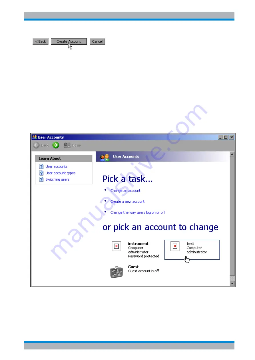
Conclude the creation of the new user by clicking the 

Create Account

 button.

The new user has now been created.

6.6.2 Changing the User Password

After the new user has been created on the instrument, the password must be adapted to the
network password. This is also done by using the User Account wizard.

Using the Windows key or the key combination 

CTRL

+

ESC

, call the Windows XP Start 

menu.

Click 

Settings

 and then 

Control Panel

 and 

User Accounts

.

The wizard for managing the users will open with the 

Pick a task...

 dialog box.

Click the desired user account (in the example: user 

Test

).

The dialog box for selecting the desired action will open.

Summary of Contents for esu

Page 1: ...R S ESU EMI Test Receiver Quick Start Guide Quick Start Guide Test Measurement 1302 6163 62 04 ...

Page 2: ...m 2 5b6 PHP http www php net PHP v 3 DOJO AJAX http www dojotoolkit org BSD License BOOST Library http www boost org Boost Software v 1 ONC RPC http www plt rwth aachen de SUN TightVnc http www tightvnc com GPL v 3 DemoForgeMirageDriver http www demoforge com dfmirage htm GPL v 3 Rohde Schwarz would like to thank the open source community for their valuable contribution to embedded computing 2009 ...

Page 3: ...f the product The product is used for its designated purpose if it is used in accordance with its product documentation and within its performance limits see data sheet documentation the following safety instructions Using the product requires technical skills and a basic knowledge of English It is therefore essential that only skilled and specialized staff or thoroughly trained personnel with the...

Page 4: ...he positions specified by the manufacturer without the product s ventilation being obstructed If the manufacturer s specifications are not observed this can result in electric shock fire and or serious personal injury or death Applicable local or national safety regulations and rules for the prevention of accidents must be observed in all work performed 1 Unless otherwise specified the following r...

Page 5: ...at it is in proper operating condition By taking appropriate safety measures and carefully laying the power cable you can ensure that the cable will not be damaged and that no one can be hurt by for example tripping over the cable or suffering an electric shock 6 The product may be operated only from TN TT supply networks fused with max 16 A higher fuse only after consulting with the Rohde Schwarz...

Page 6: ... damage may occur It is the responsibility of the employer operator to select suitable personnel for operating the products 2 Before you move or transport the product read and observe the section titled Transport 3 As with all industrially manufactured goods the use of substances that induce an allergic reaction allergens such as nickel cannot be generally excluded If you develop an allergic react...

Page 7: ... sunlight must be avoided Keep cells and batteries clean and dry Clean soiled connectors using a dry clean cloth 3 Cells or batteries must not be short circuited Cells or batteries must not be stored in a box or in a drawer where they can short circuit each other or where they can be short circuited by other conductive materials Cells and batteries must not be removed from their original packaging...

Page 8: ... regulations must be observed Also observe the relevant safety instructions in the product documentation The improper disposal of hazardous substances or fuels can cause health problems and lead to environmental damage Informaciones elementales de seguridad Es imprescindible leer y observar las siguientes instrucciones e informaciones de seguridad El principio del grupo de empresas Rohde Schwarz c...

Page 9: ...s imprescindible leer detalladamente y comprender por completo las siguientes informaciones de seguridad antes de usar el producto y respetarlas durante el uso del producto Deberán tenerse en cuenta todas las demás informaciones de seguridad como p ej las referentes a la protección de personas que encontrarán en el capítulo correspondiente de la documentación del producto y que también son de obli...

Page 10: ...por el fabricante respecto a los estados operativos y posiciones de funcionamiento sin que se obstruya la ventilación Si no se siguen las indicaciones del fabricante pueden producirse choques eléctricos incendios y o lesiones graves con posible consecuencia de muerte En todos los trabajos deberán ser tenidas en cuenta las normas nacionales y locales de seguridad del trabajo y de prevención de acci...

Page 11: ...red eléctrica Si los productos sin interruptor están integrados en bastidores o instalaciones se deberá colocar el interruptor en el nivel de la instalación 5 No utilice nunca el producto si está dañado el cable de conexión a red Compruebe regularmente el correcto estado de los cables de conexión a red Asegúrese mediante las medidas de protección y de instalación adecuadas de que el cable de conex...

Page 12: ...o ya se hayan producido condensaciones sobre el producto o en el interior de éste como p ej al desplazarlo de un lugar frío a otro caliente La entrada de agua aumenta el riesgo de choque eléctrico 18 Antes de la limpieza desconecte por completo el producto de la alimentación de tensión p ej red de alimentación o batería Realice la limpieza de los aparatos con un paño suave que no se deshilache No ...

Page 13: ...hwarz Si se reponen partes con importancia para los aspectos de seguridad p ej el enchufe los transformadores o los fusibles solamente podrán ser sustituidos por partes originales Después de cada cambio de partes relevantes para la seguridad deberá realizarse un control de seguridad control a primera vista control del conductor de protección medición de resistencia de aislamiento medición de la co...

Page 14: ...s personales o daños en el producto siga las instrucciones de seguridad del fabricante del medio de transporte o elevación utilizado 3 Si se utiliza el producto dentro de un vehículo recae de manera exclusiva en el conductor la responsabilidad de conducir el vehículo de manera segura y adecuada El fabricante no asumirá ninguna responsabilidad por accidentes o colisiones No utilice nunca el product...

Page 15: ... only be disposed of at a Rohde Schwarz service center or at a suitable depot Normas de Seguridad para Baterías Según BattV Este equipo lleva una batería que contiene sustancias per judiciales que no se debe desechar en los contenedores de basura domésticos Después de la vida útil la batería sólo se podrá eliminar en un centro de servicio de Rohde Schwarz o en un depósito apropiado Consignes de sé...

Page 16: ...ance with EN 50419 Once the lifetime of a product has ended this product must not be disposed of in the standard domestic refuse Even disposal via the municipal collection points for waste electrical and electronic equipment is not permitted Rohde Schwarz GmbH Co KG has developed a disposal concept for the environmental friendly disposal or recycling of waste material and fully assumes its obligat...

Page 17: ... management system is certified according to standards such as ISO9001 and ISO14001 Environmental commitment Energy efficient products J J Continuous improvement in J J environmental sustainability ISO14001 certified environmental J J management system Cher client Vous avez choisi d acheter un pro duit Rohde Schwarz Vous disposez donc d un produit fabriqué d après les méthodes les plus avancées Le...

Page 18: ...roximation of the laws of the Member States relating to electrical equipment for use within defined voltage limits 2006 95 EC relating to electromagnetic compatibility 2004 108 EC Conformity is proven by compliance with the following standards EN 61010 1 2001 EN 61326 1 2006 EN 61326 2 1 2006 EN 55011 2007 A2 2007 Klasse B EN 61000 3 2 2006 EN 61000 3 3 1995 A1 2001 A2 2005 For the assessment of e...

Page 19: ...nd an e mail to the Customer Support Center stating your instrument and your wish We will take care that you will get the right information USA Canada Monday to Friday except US public holidays 8 00 AM 8 00 PM Eastern Standard Time EST Tel from USA 888 test rsa 888 837 8772 opt 2 From outside USA 1 410 910 7800 opt 2 Fax 1 410 910 7801 E mail CustomerSupport rohde schwarz com East Asia Monday to F...

Page 20: ...bH Graf Zeppelin Straße 18 D 51147 Köln GEDIS GmbH Sophienblatt 100 D 24114 Kiel HAMEG Instruments GmbH Industriestraße 6 D 63533 Mainhausen Locations Worldwide Please refer to our homepage www rohde schwarz com Sales Locations Service Locations National Websites Phone 49 89 41 29 0 Fax 49 89 41 29 121 64 info rs rohde schwarz com Phone 49 83 31 1 08 0 49 83 31 1 08 1124 info rsmb rohde schwarz co...

Page 21: ...n in a 19 Rack 2 5 2 1 4 Connecting the Instrument to the AC Power Supply 2 6 2 1 5 Switching On the R S ESU 2 6 2 1 6 Functional Test 2 6 2 1 7 Switching Off the R S ESU 2 7 2 1 8 Cleaning the Outside 2 8 2 2 Instrument Drive Usage 2 8 2 3 Connecting External Devices 2 9 2 3 1 Connecting an External Keyboard 2 9 2 3 2 Connecting a Mouse 2 11 2 3 3 Connecting an External Monitor 2 12 2 3 4 Connect...

Page 22: ...nterface 2 30 2 5 1 Connecting the Instrument to the Network 2 30 2 5 2 Configuring the Network Card 2 30 2 5 2 1 Driver Installation 2 30 2 5 2 2 Configuring the Interface 2 31 2 5 2 3 Configuring Existing Network Protocols TCP IP Protocol 2 31 2 5 2 4 Installing Additional Network Protocols and Services 2 35 2 5 3 Login 2 35 2 6 Operating System Properties 2 35 2 6 1 Properties Specific to Windo...

Page 23: ...nts 5 24 5 6 Measuring Signal Spectra with Multiple Signals 5 27 5 6 1 Separating Signals by Selecting the Resolution Bandwidth 5 27 5 6 1 1 Separating Two Signals with a Level of 30 dBm each at a Frequency Spacing of 30 kHz 5 27 5 6 1 2 Measuring the Modulation Depth of an AM Modulated Carrier in the Frequency Domain 5 32 5 7 Storing and Loading Instrument Settings 5 34 5 7 1 Storing an Instrumen...

Page 24: ... the R S ESU 6 34 6 7 6 Deactivating the R S ESU from the Controller 6 35 7 Brief Introduction to Remote Control 7 1 7 1 Basic Steps in Programming using the VISA Interface 7 3 7 1 1 Linking the VISA Library for Visual Basic 7 3 7 1 1 1 Programming notes 7 3 7 1 2 Initialization and Default State 7 4 7 1 2 1 Creating Global Variables 7 4 7 1 2 2 Initializing the Controller 7 5 7 1 2 3 Initializing...

Page 25: ...Trace Data 7 16 7 2 4 Storing and Loading Instrument Settings 7 18 7 2 4 1 Storing Instrument Settings 7 18 7 2 4 2 Loading Instrument Settings 7 19 7 2 4 3 Setting the Data Record for Startup Recall 7 20 7 2 5 Configuring and Starting a Printout 7 20 Appendix Appendix A Printer Interface A 1 A 1 Installing USB Printers A 2 A 2 Installing Non Plug Play Printers A 6 A 2 1 Local Printer A 6 A 2 2 Ne...

Page 26: ...R S ESU Contents 6 Quick Start Guide 1302 6163 62 04 ...

Page 27: ... of the European Union on the approximation of the laws of the Member States relating to electrical equipment for use within defined voltage limits 2006 95 EC relating to electromagnetic compatibility 2004 108 EC Conformity is proven by compliance with the following standards EN 61010 1 2001 EN 55011 1998 A1 1999 A2 2002 Class B EN 61326 1997 A1 1998 A2 2001 A3 2003 For the assessment of electroma...

Page 28: ......

Page 29: ...ided on the CD ROM For an overview of all options available for the R S ESU visit the R S ESU EMI Test Receiver Internet site Quick Start Guide This manual is delivered with the instrument in printed form and in PDF format on the CD ROM It provides the information needed to set up and start working with the instrument Basic operations and basic measurements are described Also a brief introduction ...

Page 30: ... chapters 1 and 2 Chapter 2 Getting Started see Quick Start Guide chapter 5 Chapter 3 Manual Operation see Quick Start Guide chapter 4 Chapter 4 Instrument Functions forms a reference for manual operation of the R S ESU and contains a detailed description of all instrument functions and their application Chapter 5 Remote Control Basics describes the basics for programming the R S ESU command proce...

Page 31: ...ea Also provided for download are firmware updates including the associated release notes instrument drivers current data sheets and application notes Release Notes The release notes describe the installation of the firmware new and modified functions eliminated problems and last minute changes to the documentation The corresponding firmware version is indicated on the title page of the release no...

Page 32: ...R S ESU 0 4 Quick Start Guide 1302 6163 62 04 ...

Page 33: ...de 1302 6163 62 04 1 1 R S ESU Front and Rear Panel 1 Front and Rear Panel 1 1 Front View 1 2 1 2 Function Keys on the Front Panel 1 4 1 3 Front Panel Connections 1 6 1 4 Rear View 1 10 1 5 Rear Panel Connections 1 12 ...

Page 34: ...nt Panel 3 SETUP key see Function Keys on the Front Panel 4 HCOPY key see Function Keys on the Front Panel 5 screen 6 ON standby switch see Function Keys on the Front Panel 7 hotkeys 8 softkeys 9 function keys for frequency level and markers see Function Keys on the Front Panel 10 numeric keypad units and entry keys 11 function keys for bandwidth sweep trigger and measurement functions see Functio...

Page 35: ...on R S ESU B18 see page 8 15 USB interfaces see page 8 16 RF input 1 2 see page 6 17 probe power connector supply voltage for measurement accessories see page 7 18 AF output with volume control see page 6 19 generator output option R S FSU B9 see page 22 20 TRACE key LINES key DISP key FILE key see Function Keys on the Front Panel 21 PREVIOUS key NEXT key softkey side menus 8 9 10 11 13 14 15 16 1...

Page 36: ...e measurement markers markers and delta markers In addition the following measurement functions are assigned under this key Frequency counter SIGNAL COUNT Fixed reference point for relative measurement markers REFERENCE FIXED Enlargement of the measurement area MARKER ZOOM MKR Used for search functions of the measurement markers maximum minimum of the trace Assigns the marker frequency to the cent...

Page 37: ...igger delay and gate configuration in the case of gated sweep TRACE Configures measured data acquisition CLR WRITE AVERAGE MAXHOLD MINHOLD VIEW Configures the analysis of the measurement data DETECTOR and the mathematical linking of traces TRACE MATH LINES Configures display lines and limit lines DISP Configures the screen layout one two diagrams and the diagram contents This key can also be used ...

Page 38: ...Output GEN OUTPUT 50Ω Option R S FSU B9 The output of the tracking generator is to be connected to the DUT via a cable equipped with a male N connector The female connector is available only with the tracking generator option R S FSU B9 AF OUTPUT Headphones equipped with a miniature jack plug can be connected at the AF OUTPUT female connector The internal impedance is 10 Ω The output voltage can b...

Page 39: ...ansducers Fig 1 2 Pin assignments of left hand PROBE POWER connector The right hand connector supplies the 15 V and 12 6 V supply voltages and ground This connector is suitable for supplying high impedance probes from Agilent Fig 1 3 Pin assignments of right hand PROBE POWER connector Check the volume setting carefully before putting on the headphones in order to protect your hearing Pin Signal 1 ...

Page 40: ...sh card inserted into the card slot at the front panel replaces the internal hard disk with option R S ESU B18 The R S ESU B19 provides a spare flash card Fig 1 4 Compact flash card drive option R S ESU B18 Use suitable double shielded cables Use only USB devices that keep the permissible EMI limits To ensure failure free operation it is recommended to avoid placing external cables close to the co...

Page 41: ...RCE female connector is used to switch an external noise source on and off in order for example to measure the noise figure of DUTs Conventional noise sources require a voltage of 28 V in order to be switched on They are switched off at 0 V The female connector supplies these switching voltages The output supports a maximum load of 100 mA ...

Page 42: ...ator control option R S FSP B10 see page 17 2 LAN interface see page 17 3 IF output 20 4 MHz see page 16 4 I Q input for tracking generator option R S FSU B9 see page 16 5 video output see page 16 6 reference input and output see page 15 7 user port see page 14 8 external generator control option R S FSP B10 see page 17 9 voltage output see page 14 3 5 6 2 8 7 9 14 13 12 11 10 1 4 ...

Page 43: ...interface see page 14 11 double USB interface see page 14 12 mouse interface see page 13 13 VGA interface for external monitor see page 13 14 RS232 C interface see page 12 15 LPT printer interface see page 12 16 GPIB interface for remote control see page 12 17 AC power supply connector with on off switch see page 12 17 16 15 ...

Page 44: ...panel of the R S ESU is provided for connecting a printer The interface is compatible with the CENTRONICS interface For further information refer to the Operating Manual chapter 8 RS 232 C Interface COM The instrument comes with an RS 232 C interface The interface can be manually activated and configured for remote control by defining the parameters in the COM INTERFAC table which is accessed from...

Page 45: ...n is described in the section Connecting an External Monitor on page 2 12 Fig 1 6 Pin assignments of the MONITOR connection Mouse Connection MOUSE A PS 2 connector is provided at the rear panel to connect a PS 2 mouse Fig 1 7 Pin assignments for the MOUSE connection Pin Signal Pin Signal 1 R 9 GND 2 G 10 GND 3 B 11 NC 4 NC 12 NC 5 GND 13 HSYNC 6 GND 14 VSYNC 7 GND 15 NC 8 GND Pin Signal 1 MOUSEDAT...

Page 46: ... 2 0 Fig 1 8 USB connector assignment Voltage output SWEEP At this female BNC connector sawtooth voltage proportional to the frequency is provided The output voltage ranges from 0 to 5 V USER PORT The user interface is a 25 pin Cannon connector which provides access to the user port The port is 8 bits wide A0 A7 and can be configured either as output or as input The voltage levels are TTL levels L...

Page 47: ...z reference signal The required input level is 0 to 10 dBm The REF OUT female connector provides the internal 10 MHz reference signal with a 0 dBm output level for other devices The SETUP menu is used to select between the internal and external references If an external reference is used for operation the external reference signal from REF IN is looped through to REF OUT Pin Signal Range of values...

Page 48: ...g on the instrument has no effect on the video output The usable video bandwidth is limited only by the set resolution bandwidth RBW to approximately RBW The output voltage is always logarithmic independent of the selected scaling on the display Likewise the selected detectors e g RMS affect only the display but not the video output The output impedance is 50 Ω All subsequent voltage values are ty...

Page 49: ...ontrol the instrument provides a second GPIB interface for using external generators Fig 1 9 Pin assignment of the second IEC interface AUX CONTROL Option R S FSP B10 If option R S FSP B10 external generator control is built in the R S ESU provides a female connector that allows measurement data acquisition to be synchronized with the output signal of a Rohde Schwarz generator The R S ESU remote c...

Page 50: ...6163 62 04 Fig 1 10 Pin assignment of the AUX CONTROL connector Pin Signal Description 1 n c not connected 2 BLANK Return signalling from the signal generator indicating that frequency setting is completed 3 TRIGGER Trigger signal for switching to the next frequency 6 9 GND Ground ...

Page 51: ...ing the Instrument to the AC Power Supply 2 6 2 1 5 Switching On the R S ESU 2 6 2 1 6 Functional Test 2 6 2 1 7 Switching Off the R S ESU 2 7 2 1 8 Cleaning the Outside 2 8 2 2 Instrument Drive Usage 2 8 2 3 Connecting External Devices 2 9 2 3 1 Connecting an External Keyboard 2 9 2 3 2 Connecting a Mouse 2 11 2 3 3 Connecting an External Monitor 2 12 2 3 4 Connecting a Printer 2 13 2 3 5 Connect...

Page 52: ...2 2 4 4 Setting the Screen Colors 2 22 2 4 5 Automatically Switching Off the Internal Screen 2 24 2 4 6 File and Path Selection Using the Front Panel Keys 2 25 2 4 7 Selecting and Configuring Printers 2 27 2 4 7 1 Selecting Alternative Printer Configurations 2 28 2 4 7 2 Selecting Printer Colors 2 28 2 4 8 Installing Plug Play Printers 2 29 2 4 9 Installing Non Plug Play Printers 2 30 2 5 Configur...

Page 53: ...3 62 04 2 3 R S ESU Preparing for Use 2 6 1 Properties Specific to Windows XP 2 35 2 6 1 1 Windows XP Service Packs 2 36 2 6 1 2 Opening the Windows XP Start Menu 2 36 2 6 1 3 Windows XP Software Approved for the Instrument 2 36 ...

Page 54: ...ble to keep the original packing material in order to prevent control elements and connectors from being damaged in case the instrument is to be transported or shipped at a later date Protective plastic caps for the front panel and the rear panel can be ordered addditionally order number 1096 7095 00 Please note that you need to order 2 covers for 1 instrument 2 1 2 Setting Up the Instrument The i...

Page 55: ...damage of electronic components the operational site must be protected against electrostatic discharge ESD The following two methods of ESD protection may be used together or separately Wrist strap with cord to ground connection Conductive floor mat and heel strap combination When the instrument is installed in a rack make sure that the vents for air inflow on the side panel and the air outlets on...

Page 56: ... that were present when the instrument was last switched off 2 1 6 Functional Test Call self alignment with the CAL key CAL TOTAL softkey Once the system correction values have been calculated successfully the message Calibration Passed will appear AC power connector Connect the R S ESU to the AC power supply using the power cable that is supplied Since the instrument is assembled in line with the...

Page 57: ...strument is switched on because the instrument saves the values and loads them during booting automatically A self alignment is recommended if the instrument is used at a temperature that differs considerable more than 10 C from the temperature present at the last self alignment The self test also does not need to be repeated every time the instrument is switched on It is necessary only when instr...

Page 58: ...r config is the default location for customized instrument settings D R_S instr temp is the default directory for hardcopy files Other user data should be stored on drive D E Backup storage location for Windows XP Here a copy of the operating system is saved This drive is used to restore Windows XP using Analyzer Firmware Backup function on Power On A copy of the currently installed update sets ar...

Page 59: ... selecting START SETTINGS CONTROL PANEL KEYBOARD International Keyboard Support As of firmware version 4 3x the following international keyboard drivers are supported French Keyboards German Keyboards Italian Keyboards Portuguese Keyboards Spanish Keyboards These drivers are already installed on the R S ESU if it is shipped with firmware version 4 3x or later A separate installer file is available...

Page 60: ...ing External Devices 2 10 Quick Start Guide 1302 6163 62 04 5 Select Settings Control Panel Regional and Language Options Languages 6 Select Details 7 Select Add and choose one of the available languages Confirm your selection with OK ...

Page 61: ...u to connect a mouse to one of the USB interfaces on the front or rear panel or the PS 2 mouse connector on the rear panel Mouse devices from Microsoft and Logitech are supported After being connected the mouse is automatically detected Special settings such as mouse cursor speed etc can be made in the Windows XP Start menu by selecting START SETTINGS CONTROL PANEL MOUSE If you use a keyboard that...

Page 62: ...trument you have to activate it This requires a mouse and an external keyboard the connection is described in sections Connecting a Mouse on page 2 11 and Connecting an External Keyboard on page 2 9 Make sure that the external monitor is connected Press the CTRL ESC key combination to display the taskbar On the right side of the taskbar click the monitor icon Select Graphics Options Output To Inte...

Page 63: ...xpansions that are possible with the R S ESU The following list shows various USB devices that can be useful for the R S ESU Power sensors of the R S NRP Zxx series require adapter cable R S NRP Z4 Memory stick for easy transfer of data to from a PC e g firmware updates CD ROM drives for easy installation of firmware applications PC keyboard for entering comments file names etc Mouse for easy oper...

Page 64: ...orresponding driver Example Connect a memory stick to the R S ESU 1 When you connect the pendrive at the USB interface Windows XP detects the new hardware 2 Windows XP installs the corresponding driver If installation is successful Windows XP informs you that the device is ready to use The memory stick is made available as a new drive and is displayed in the Windows Explorer The memory stick can b...

Page 65: ...tors it is also controlled via the TTL synchronization interface that is contained in the AUX CONTROL interface of the R S ESU Using the TTL interface allows you to attain significantly higher speeds than possible with a pure GPIB control because the frequency switching mechanism of the R S ESU is directly coupled to the frequency switching mechanism of the generator To increase measurement accura...

Page 66: ...belling on the TRIGGER MARKER and BLANK lines Alternative 3 R S SML R S SMG SMGU R S SMH SMHU R S SMX SMY generators from other manufacturers No TTL connection possible The generator type determines which one of the possible connections is suitable for the generator For more information refer to the Operating Manual for the generator 3 Connect the reference frequency output of the generator to the...

Page 67: ...g the Ur key move the selection bar to the GPIB ADDR column and press the ENTER key The entry field for the GPIB address of the generator will open Enter the GPIB address of the generator and confirm with ENTER The specified address will be added to the table 3 Select the reference frequency for the generator If you want to operate the generator using its internal reference change the GEN REF soft...

Page 68: ...a Tracking Generator To activate the external generator as a tracking generator do the following Switch on the external generator Press the SPECTRUM hotkey to change to the analyzer mode Press the NETWORK hotkey on the R S ESU Press the EXT SOURCE softkey Tracking generator operation using an external generator will be activated The external generator will switch to remote control and can be used ...

Page 69: ...UP menu will open Press the GENERAL SETUP softkey The submenu with general settings will open The TIME DATE softkey activates the TIME AND DATE table for entering the time and date for the internal real time clock Entering the time Hours and minutes can be entered independently of each other in the entry field IEC bus command SYST TIME 12 30 If the reference signal is missing when switchover to th...

Page 70: ... 2 4 3 Setting the GPIB Interface Press the SETUP key The SETUP menu will open Press the GENERAL SETUP softkey The submenu with general settings will open Press the GPIB softkey The submenu for setting the parameters of the remote control interface will open 2 4 3 1 GPIB Address Press the GPIB ADDRESS softkey The entry field for the GPIB address will open The setting range is from 0 to 30 The defa...

Page 71: ... rules which are different from syntax rules of the SCPI mode Correspondingly proper detection of SCPI commands is not ensured in this mode For 8566A B 8568A B and 8594E command sets A and B are available Command sets A and B differ in the rules regarding the command structure Selecting a language different from SCPI will set the GPIB address to 18 if it was 20 before Start stop frequency referenc...

Page 72: ...8563E 601 0 Hz 26 5 GHz 0 dBm AC 8564E 601 0 Hz 40 GHz 0 dBm AC 8565E 601 0 Hz 50 GHz 0 dBm AC 8566A B 1001 2 GHz 22 GHz 0 dBm DC R S ESU 8568A B 1001 0 Hz 1 5 GHz 0 dBm AC 8591E 401 0 Hz 3 GHz 0 dBm AC 8594E 401 0 Hz 3 GHz 0 dBm AC 71100C 1001 2 GHz 22 GHz 0 dBm DC R S ESU 71200C 1001 2 GHz 22 GHz 0 dBm DC R S ESU 71209A 1001 2 GHz 22 GHz 0 dBm DC R S ESU Note regarding the selection of 856x for ...

Page 73: ...activates the selection of screen elements for which the color setting needs to be changed Once this selection is made the PREDEFINED COLORS BRIGHTNESS TINT and SATURATION softkeys can be used to change the overall color or the brightness tint and color saturation of the selected element The BRIGHTNESS softkey activates entry of the brightness of the selected graphics element The entry value is be...

Page 74: ...e made from the front panel after the selected response time key softkey or hardkey and rotary knob To activate automatic switch off Press the DISP key Press the CONFIG DISPLAY softkey Press the DISPLAY PWR SAVE softkey The softkey will have a color background indicating that the power save mode is active At the same time the input window for the response time will open Enter the desired response ...

Page 75: ...EXPORT as an example Press the TRACE key and then the NEXT softkey Press the ASCII FILE EXPORT softkey to open the corresponding dialog box The focus is on the File Name field so you can directly edit the file name using the numeric keys the cursor keys or the BACK key You can also use alphanumeric characters in the file name To enter alphanumeric characters select the EDIT FILENAME button Confirm...

Page 76: ...until the focus is on the Save In field Press the CURSOR RIGHT key to open the dropdown menu and select the drive you want to save the file to with the CURSOR UP and CURSOR DOWN keys Confirm your selection by pressing the ENTER key Select a subfolder by moving the rotary knob until the file subfolder list is in focus The selected file or subfolder in focus is framed by dotted line Use the CURSOR U...

Page 77: ...selection by pressing the rotary knob or the ENTER key After you confirm the selection the entries Name Print to File and Orientation will be made available and can also be accessed with the rotary knob To select the printer type open the selection list by pressing the rotary knob or the ENTER key after you access the Name field From the selection list you can now select the printer you want in th...

Page 78: ...ive Printer Configurations The R S ESU can support two independent hardcopy settings This allows you to quickly switch between output to a file and a printer To make a selection use the DEVICE 1 2 softkey which simultaneously shows the associated setting when the Hardcopy Setup dialog box is open IEC bus command 2 4 7 2 Selecting Printer Colors The COLORS softkey opens the submenu for selecting th...

Page 79: ...ug play printers can be easily installed under Windows XP After you connect and switch on a printer Windows XP automatically detects the printer and installs the associated driver provided that the driver is contained in the Windows XP installation If Windows XP does not find the printer driver it will prompt you to enter a path for the associated installation files In addition to the pre installe...

Page 80: ...al RJ 45 cable not supplied to the rear panel of the instrument and a network hub of the required LAN segment Since the RJ 45 involves star configuration rather than bus cabling no special measures need to be taken Setting up the connection does not cause any problems on the network Likewise disconnecting the instrument from the network does not cause any problems as long as no data traffic to and...

Page 81: ...etwork Protocols TCP IP Protocol on page 2 31 IEC bus command 2 5 2 3 Configuring Existing Network Protocols TCP IP Protocol Before starting check whether your network a DHCP server If necessary ask your network administrator If your network has a DHCP server the IP address is to be requested from a DHCP server automatically This is the default setting and no change of configuration is necessary I...

Page 82: ...tings Network Connections Local Area Connection The Local Area Connection Status dialog box will open Windows XP automatically appends numbers to the name Local Area Connection Status e g Local Area Connection Status 8 if the configuration is set up using the New Connection wizard These numbers are not important in the following configuration steps and are therefore omitted ...

Page 83: ...w with the available network protocols opens Click the network protocol you want TCP IP in the example Click the Properties button The dialog box with the settings for the selected network protocol will open By default Obtain an IP address automatically is selected Select Use the following IP address to enter a predefined IP address ...

Page 84: ...check the entered settings for correctness and then store the configuration If you have entered an invalid IP address or subnet mask an error message will appear that also asks you whether you want to enter a different address or mask Click Yes The dialog box for entering the TCP IP parameters will open again If all settings are correct you will be prompted to restart the instrument if required by...

Page 85: ...ument lowercase are set For information on how to deactivate the automatic login refer to chapter LAN Interface section Deactivating the Automatic Login Mechanism on page 6 14 2 6 Operating System Properties 2 6 1 Properties Specific to Windows XP The instrument contains the Windows XP operating system To ensure that the instrument software functions properly certain rules must be adhered to when ...

Page 86: ... only if software and hardware approved or offered by Rohde Schwarz are used Using other software or hardware may cause the functions of the R S ESU to perform improperly or fail The following program packages have been successfully tested for compatibility with the measurement instrument software R S FS K3 Software for measuring noise factor and gain R S FS K4 Software for measuring phase noise P...

Page 87: ...stem Properties R S Power Viewer virtual power meter for displaying results of the power sensors of the R S NRP Zxx series Windows XP Remote Desktop FileShredder For reliable deletion of files on the hard disk Symantec Norton AntiVirus Virus protection software McAfee Virusscan ...

Page 88: ...R S ESU Preparing for Use Operating System Properties 2 38 Quick Start Guide 1302 6163 62 04 ...

Page 89: ...Start Guide 1302 6163 62 04 3 1 R S ESU Firmware Update and Installation of Firmware Options 3 Firmware Update and Installation of Firmware Options 3 1 Firmware Update 3 2 3 2 Activating Firmware Options 3 3 ...

Page 90: ...ectory for installing or uninstalling new firmware versions will open Press the UPDATE PATH softkey The entry field for the path with the set of update directories will open Enter the drive name and directory and confirm with ENTER Example The firmware update files are stored on a memory stick in the Update directory They are allocated in the Disk1 to Disk n subdirectories After you insert the mem...

Page 91: ...ailable are listed in a table that is displayed when the submenu is opened Press the INSTALL OPTION softkey The field for entering the license key for the firmware option now appears After you enter a valid license key OPTION KEY OK will appear in the message line and the option will be entered in the FIRMWARE OPTIONS table If you enter an invalid license key the message OPTION KEY INVALID will ap...

Page 92: ...R S ESU Firmware Update and Installation of Firmware Options Activating Firmware Options 3 4 Quick Start Guide 1302 6163 62 04 ...

Page 93: ...ayout 4 2 4 1 1 Displays in the Diagram Area 4 3 4 2 Setting Parameters 4 7 4 2 1 The Keypad 4 7 4 2 2 The Rotary Knob and Arrow Keys 4 8 4 2 3 Editing Numeric Parameters 4 8 4 2 4 Editing Alphanumeric Parameters 4 9 4 2 4 1 Alphanumeric Editor Type 1 4 9 4 2 4 2 Alphanumeric Editor Type 2 4 10 ...

Page 94: ...2 04 4 1 Diagram Layout Fig 4 1 Screen layout of the R S ESU during analyzer operation Logo title date Hardware settings Marker Delta marker Status information Trace information Level axis labelling Frequency axis labelling Dirty flag Enhancement labels Marker Delta marker ...

Page 95: ...me that has been set SWEEP TIME If the sweep time does not correspond to the value for automatic coupling an asterisk will appear in front of the field The color of the asterisk will turn to red if the sweep time is set below the value for automatic coupling In this case the sweep time must be increased Marker Delta Contains the x and y axis positions of the last marker or delta marker that was se...

Page 96: ...cates an overload of the input mixer Increase the RF attenuation IFOVL Indicates an overload of the IF signal path after the input mixer Increase the reference level LOUNL Indicates that an error was detected in the instrument s frequency processing hardware EXREF Is displayed if the instrument was set to an external reference but no signal was detected on the reference input OVEN Indicates that t...

Page 97: ...RM RMS detector QP QUASIPEAK detector auto manual The selected detector does not match the one for automatic coupling Trace Mode Display of the sweep mode CLRWR CLEAR WRITE MAXH MAX HOLD MINH MIN HOLD AVG AVERAGE VIEW VIEW Trace Mathematics Indicates that the trace difference function is activated e g 1 3 in the example means that trace 3 is subtracted from trace 1 1 PK CLRWR 1 3 Trace number Dete...

Page 98: ...isplay remains on screen until the user eliminates the cause In some cases this involves starting a new sweep SINGLE SWEEP mode or switching the affected trace to BLANK A B Designation for screen A B If screen A B is activated for entering measurement parameters the label background will be in color SGL The sweep is set to SINGLE SWEEP GAT The frequency sweep is controlled via the EXT TRIG GATE co...

Page 99: ...B or dimensionless values all units have the value 1 as multiplying factor Thus they have the same function as an ENTER key The same is true for an alphanumeric entry In addition the unit keys open and close selection fields in tables subtables BACK key If a numeric entry has already been started this key deletes the character to the left of the cursor If an entry has been completed or not yet sta...

Page 100: ... functions Increments clockwise direction or decrements counterclockwise direction the instrument parameter at a defined step width in the case of a numeric entry Shifts the selection bar horizontally or vertically within tables as long as an entry field is not open The arrow keys are used to change the direction of motion horizontal vertical Selects the individual letters when the alphanumeric ed...

Page 101: ... cursor now marks the first letter of the editor Using the Ul and Ur arrow keys or the rotary knob place the cursor on the character that you want to enter in the editing line Press either the ENTER key or the rotary knob The character will be added to the editing line Correcting the entry Using the Uu arrow key place the cursor in the editing line Using the Ul and Ur arrow keys or the rotary knob...

Page 102: ...first character of the editor Using the Ul and Ur arrow keys or the rotary knob place the cursor on the character that you want to enter in the editing line Press the ENTER key or the rotary knob The character will be added to the editing line Correcting the entry alternative 1 Using the rotary knob go to the character in the character selection field By pressing the rotary knob on and place the c...

Page 103: ... field will close and the new entry will be accepted by the instrument Completing the entry alternative 2 Using the Uu arrow key place the cursor by the editing line Press one of the unit keys or the rotary knob The data entry field will close and the new entry will be accepted by the instrument Cancelling the entry Press the ESC key The data entry field will close and the previous entry will be r...

Page 104: ...R S ESU Basic Operation Setting Parameters 4 12 Quick Start Guide 1302 6163 62 04 ...

Page 105: ...Counter 5 19 5 4 Measuring Harmonics of Sinusoidal Signals 5 21 5 4 1 Measuring the Suppression of the First and Second Harmonic of an Input Signal 5 21 5 4 2 Reducing Noise 5 22 5 5 Measuring Harmonics with Frequency Sweeps 5 24 5 5 1 High Sensitivity Harmonics Measurements 5 24 5 6 Measuring Signal Spectra with Multiple Signals 5 27 5 6 1 Separating Signals by Selecting the Resolution Bandwidth ...

Page 106: ...uration without Traces 5 34 5 7 1 1 Storing Traces 5 35 5 7 2 Loading an Instrument Configuration 5 35 5 7 2 1 Automatic Loading of a Data Record during Booting 5 36 5 8 Printing Out the Measurement Results 5 37 5 8 1 Selecting the Color Setting for the Printout 5 37 5 9 Additional Measurement Examples 5 38 ...

Page 107: ...mple measurement task for an EMI test receiver Each operating step is explained with the aid of R S ESU for rapid familiarization of the user without the need to know all the details of the operating functions In the introductory example a standard measurement of level and frequency is performed with the aid of the SCAN TABLE This measurement is an overview and pre certification measurement to be ...

Page 108: ... BW setting the measurement time MEAS TIME and selecting the detectors e g peak or average and MARKER functions required for the analysis Measurement Sequence Level and Frequency Measurement In this example the spectrum of the signal present at RF INPUT is recorded in the frequency range 150 kHz to 30 MHz The SCAN TABLE and associated parameters are manually set The example is generally suitable f...

Page 109: ...the peak search functions 8 Set the SPLIT SCREEN function 9 Tune the receiver frequency and obtain final test results using the QUASIPEAK detector 10 From overview to standard conformal measurement 11 Store the test results tables or diagrams Detailed procedure 1 Reset the instrument Press the PRESET key 2 Select the receiver mode Press the RECEIVER hotkey The receiver mode is set The main receive...

Page 110: ...d and divided into scan subranges Fig 5 2 Scan range after selecting default setup with PRESET After PRESET a scan range of 30 MHz to 1 GHz is set on the frequency axis The stop frequency is set to 1 GHz Press the Ud arrow key repeatedly until a line is marked in the SCAN TABLE Press the Ur arrow key field An entry in the RANGE 2 column is marked Press the DELETE RANGE softkey All entries in the R...

Page 111: ...y display has to be adapted to the new settings The lowest start frequency of the range 1 scan and the highest stop frequency of the subsequently defined subranges are used for defining the start and stop frequencies of the graphics display In the example the limit frequencies of SCAN RANGE 1 are therefore also the limits of the graphics display Press the menu change key PREV The TDOMAIN SCAN subm...

Page 112: ...ess the TRACE key The TRACE menu is displayed Press the SELECT TRACE softkey A data input field is displayed Enter 1 as trace number and confirm with the ENTER key Press the DETECTOR softkey The DETECTOR menu is displayed Press the MAX PEAK softkey to select the detector The peak detector is selected for trace 1 Press the TRACE key again Press the SELECT TRACE softkey again Enter 2 as trace number...

Page 113: ...ig 5 4 should be further analyzed with the aid of the built in marker functions Depending on the DUT diverse trace forms are obtained For this reason the diagram below should be regarded as an example The scaling of the y axis can be adjusted in the AMPT menu by means of softkey GRID RANGE LOG MANUAL if necessary Fig 5 4 Result display of standard pre compliance measurement using peak average dete...

Page 114: ...KR key The MKR menu is displayed Press the PEAK softkey The marker is positioned at the maximum level in the display Press the menu change key NEXT Press the NEXT MIN softkey The marker moves to the next lower level in the spectrum irrespective of whether the frequency is higher or lower than that of the previously measured PEAK value Press the menu change key PREV Press the NEXT PEAK RIGHT softke...

Page 115: ...e SPLIT SCREEN function The SPLIT SCREEN function simplifies the analysis of measured data particularly at critical frequencies In the split screen mode the frequency e g that of the active marker and the level of the active detectors are displayed in the upper half of the screen numerically and on a bar graph Press the DISP key The DISPLAY menu is displayed Press the SPLIT SCREEN softkey Two wind...

Page 116: ...he screen Press the MKR key The MKR menu is displayed Press the TUNE TO MARKER softkey The current receive frequency is tuned to the marker frequency A measurement time of 1 s must be set for measurements to standard Press the RECEIVER hotkey The RECEIVER menu is displayed Press the MEAS TIME softkey The window with the currently set measurement time is displayed 1 ms in the example Enter 1 on the...

Page 117: ... chapter 4 Limit lines A final measurement to standard can be performed when active limit lines are displayed in the diagram during the described analysis and measurements are repeated at all critical frequencies using the standard measurement time and a corresponding detector For details refer to the Operating Manual chapter 4 Transducer Care should be taken that the correction values or transduc...

Page 118: ... Connect a memory stick to the USB port Press the PRINT SCREEN softkey The output is started A window to enter file name and path Enter file name and path using the built in auxiliary line editor or the external keyboard e g F display wmf and confirm the entry with the ENTER key Press the ENTER key The screen content is stored on the memory stick under the specified file name During storing the so...

Page 119: ...uency Measurement Fig 5 7 Result display stored in a file in WMF format A detailed description of the file management for complete EMI Test Receiver setups data records for traces traces 1 3 limit lines and transducer is given in the Operating Manual chapter 4 section Operating Concept of File Managers ...

Page 120: ... marker position The frequency measurement uncertainty is determined by the reference frequency of the R S ESU the resolution of the marker frequency display and the resolution of the screen 5 3 1 1 Procedure 1 Reset the instrument Press the PRESET key Press the SPECTRUM hotkey 2 Connect the signal to be measured to the RF INPUT input on the instrument front panel 3 Set the center frequency to 128...

Page 121: ... T1 Trace 1 5 3 1 2 Increasing the Frequency Resolution The frequency resolution of the marker is predefined by the measurement point resolution of the trace A trace uses 625 measurement points i e when the frequency span is 1 MHz each measurement point corresponds to a span of approx 1 6 kHz This corresponds to a maximum uncertainty of 0 8 kHz You can increase the measurement point resolution of ...

Page 122: ...MPT key The AMPT menu will appear in the softkey bar The REF LEVEL softkey will be highlighted in red to indicate that it is activated for data entry The entry field for the reference level is also opened and displays a value of 20 dBm Using the numeric keypad enter 30 and confirm the entry with the dBm key The reference level is now set to 30 dBm The maximum of the trace is near the maximum of th...

Page 123: ...RUM hotkey 2 Set the center frequency and the span Press the FREQ key and enter 128 MHz The center frequency of the R S ESU is set to 128 MHz Press the SPAN softkey and enter 1 MHz The frequency span of the R S ESUs set to 1 MHz 3 Activate the marker Press the MKR key The marker is activated and set to the signal maximum The level and the frequency of the marker are displayed in the marker informa...

Page 124: ...ove the noise level to ensure that the specified measurement accuracy is adhered to For bandwidths between 200 kHz and 10 MHz the time for measuring the frequency is inversely proportional to the selected resolution i e a resolution of 1 Hz requires a gate time of 1 second for the counter For digital bandwidths of less than 300 kHz the time for measuring the frequency is always approx 30 ms and is...

Page 125: ...cond harmonics of the input signal 3 For maximum sensitivity set the RF attenuation to 0 dB Press the AMPT key Press the RF ATTEN MANUAL softkey and enter 0 dB 4 To average suppress the noise reduce the video bandwidth Press the BW key Press the COUPLING RATIO softkey Using the arrow keys select RBW VBW NOISE 10 The video bandwidth VBW will now always be set to less than the resolution bandwidth R...

Page 126: ...f the internal reference generator Markers delta 2 T1 and delta 3 T1 show the offset of the first and second harmonics from the fundamental 5 4 2 Reducing Noise The R S ESU offers three means of effectively differentiating the harmonics of a signal from the noise Reducing the video bandwidth Averaging the trace Reducing the resolution bandwidth Reducing the video bandwidth and averaging the traces...

Page 127: ...l increase to 25 ms In other words the measurement will clearly take more time The video bandwidth that is shown in the display is marked with an asterisk VBW to indicate that it is no longer coupled to the resolution bandwidth see Fig 5 10 Fig 5 10 Suppression of noise during harmonics measurement by reducing video bandwidth 2 Recouple the video bandwidth to the resolution bandwidth Press the VID...

Page 128: ...ds 7 Reset the resolution bandwidth couple it to the span Press the RES BW AUTO softkey 5 5 Measuring Harmonics with Frequency Sweeps There are advantages in performing harmonic measurements with a single frequency sweep provided that the harmonic distance is in a way that a resolution bandwidth can be selected which is wide enough to give an acceptably short sweep time 5 5 1 High Sensitivity Harm...

Page 129: ...er 1 will be activated and positioned to the signal maximum fundamental at 128 MHz The level and frequency of the marker will be displayed in the marker information field 5 Set the measured signal frequency and the measured level as reference values Press the REFERENCE FIXED softkey The position of the marker becomes the reference point The reference point level is indicated by a horizontal line t...

Page 130: ...equal to the marker frequency 7 Set the center frequency to the 2nd harmonic of the signal Press the FREQ key Press the up arrow key once The center frequency is set to the 2nd harmonic 8 Place the delta marker on the 2nd harmonic Press the MKR key Press the PEAK softkey The delta marker jumps to the maximum of the 2nd harmonic The displayed level result is relative to the reference point level fu...

Page 131: ... sinusoidal signal will be shown on the screen by means of the passband characteristic of the resolution filter RBW that has been set Its specified bandwidth is the 3 dB bandwidth of the filter Two signals with the same amplitude can be resolved if the resolution bandwidth is smaller than or equal to the frequency spacing of the signals If the resolution bandwidth is equal to the frequency spacing...

Page 132: ...to 30 kHz and the video bandwidth to 1 kHz Press the BW key Press the RES BW MANUAL softkey and enter 30 kHz Press the VIDEO BW MANUAL softkey and enter 1 kHz The two signals can be clearly distinguished by a 3 dB level drop in the center of the screen Level Frequency Signal generator 1 30 dBm 100 00 MHz Signal generator 2 30 dBm 100 03 MHz The video bandwidth is set to 1 kHz in order to make the ...

Page 133: ...sized RF sinusoidal signals with the resolution bandwidth which corresponds to the frequency spacing of the signals The level drop is located exactly in the center of the screen only if the generator frequencies exactly match the frequency display of the R S ESU To achieve exact matching the frequencies of the generators and the R S ESU must be synchronized ...

Page 134: ...MANUAL softkey and enter 100 kHz It is no longer possible to clearly distinguish the two generator signals Fig 5 14 Measurement of two equally sized RF sinusoidal signals with a resolution bandwidth which is larger than their frequency spacing The resolution bandwidth RBW can be reduced again by turning the rotary knob counterclockwise thus yielding a higher frequency resolution ...

Page 135: ... a rate of 1 RBW2 At smaller bandwidths 10 dB per a bandwidth factor of 10 the noise display decreases simultaneously Fig 5 15 Measurement of two RF equally sized sinusoidal signals with a resolution bandwidth 1 kHz which is clearly smaller than their frequency spacing 6 Activate the FFT bandwidths Using the FILTER TYPE softkey in the selection list set the filter type to FFT IF filtering is now p...

Page 136: ...he Frequency Domain In the frequency range scan display the AM side bands can be resolved with a narrow bandwidth and measured separately The modulation depth of a carrier modulated with a sinusoidal signal can then be measured Since the dynamic range of an analyzer is very large extremely small modulation depths can also be measured precisely For this purpose the R S ESU provides measurement rout...

Page 137: ... for measuring the AM modulation depth Press the MEAS key Press the MODULATION DEPTH softkey The R S ESU automatically sets a marker to the carrier signal in the center of the diagram and one delta marker each to the upper and lower AM sidebands The R S ESU calculates the AM modulation depth from the level differences of the delta markers to the main marker and outputs the numeric value in the mar...

Page 138: ...rating system The preset state Current Settings includes that the settings of the measurement functions activated limit lines and the active transducer factor are stored Use the ITEMS TO SAVE RCL function to store load traces and to store additional limit lines and transducer factors 5 7 1 Storing an Instrument Configuration without Traces You can store an instrument configuration as follows Press...

Page 139: ...tion An instrument configuration can be loaded in either of the following two ways 1 By directly entering the data record name Press the FILE key and then the RECALL softkey Enter the name of the data record to be loaded which is a digit from 0 to 9 in the simplest case and press ENTER The data record will be loaded The name of a data record may contain letters and digits If necessary the desired ...

Page 140: ... ESU is switched on in the factory default state it loads the instrument settings that it had when switched off provided that it was switched off using the STANDBY switch on the front panel see chapter Switching Off the R S ESU on page 2 7 However the R S ESU can also automatically load a data record defined by the user This requires performing the following procedure Press the FILE key and then t...

Page 141: ...intout 5 8 1 Selecting the Color Setting for the Printout The COLORS submenu allows you to switch between black and white and color printouts default You can also select the color setting SCREEN Output using screen colors OPTIMIZED default Instead of the bright colors for traces and markers dark colors will be used blue for trace 1 black for trace 2 green for trace 3 turquoise for markers USER DEF...

Page 142: ...2 which provides a series of additional examples Measurement examples for the instrument s options are provided in the Operating Manuals for the individual options In the case of the SCREEN and OPTIMIZED settings the background is always printed out in white and the grid in black In the case of the USER DEFINED setting these colors can also be selected When you open the submenu the color display w...

Page 143: ...ing Users 6 9 6 6 2 Changing the User Password 6 11 6 6 3 NOVELL Network only Configure NOVELL Client 6 13 6 6 4 Logging On to the Network 6 14 6 6 5 Deactivating the Automatic Login Mechanism 6 14 6 6 6 Reactivating the Automatic Login Mechanism 6 14 6 6 7 Using Network Drives 6 15 6 6 8 Installing a Network Printer 6 17 6 6 9 Sharing Directories only with Microsoft Networks 6 21 6 7 Manual Opera...

Page 144: ...te Desktop Connection with the R S ESU 6 34 6 7 6 Deactivating the R S ESU from the Controller 6 35 In some of the following step by step instructions user names and passwords must be entered This requires a mouse and an external keyboard is the connection is described in sections Connecting a Mouse and Connecting an External Keyboard on page 2 9 ...

Page 145: ...e case of the RSIB protocol and VXI11 support TCP IP must always be installed In the following example the support for Novell Network will also be installed Windows XP automatically appends numbers to the name Local Area Connection Status e g Local Area Connection Status 8 if the configuration is created using the New Connection wizard Since these numbers are unimportant in the following configura...

Page 146: ...dditional Network Protocols Services 6 4 Quick Start Guide 1302 6163 62 04 Click the Install button The list of available network components will open Select Client Click the Add button The list of available network protocols will open ...

Page 147: ...ill be prompted to restart the instrument Click the Yes button Windows will restart the system Your network administrator knows which clients services and protocols must be installed for your network If network components are not included in D I386 they have to be installed e g using a memory stick containing the drivers or a CD that is replayed via a USB CD ROM drive In this case click the Have D...

Page 148: ...dows Start menu will open Select Settings Control Panel System The System Properties dialog will open Select the Computer Name Network Protocols Services Comments NOVELL Netware NWLink IPX SPX compatible transport Client service for NetWare The frame type used in the network must be set under Protocols Properties IP Networks FTP TELNET WWW GOPHER etc TCP IP Simple TCP IP services An IP address tha...

Page 149: ...mputer name domain and workgroup will open Enter a new computer name If necessary enter a Domain or Workgroup Confirm changes with OK You are prompted to restart the instrument Click the Yes button Windows will restart the system You can change the other settings after you select the other tabs Before doing so however be sure to check with your network administrator ...

Page 150: ...strument the Internet Connection Firewall ICF is activated for all network connections by default to enhance protection of the instrument The default configuration of the firewall enables data transfer with other controllers in a local network file and printer sharing and remote control via LAN To change these settings for security reasons perform the following steps Using the Windows key or the k...

Page 151: ...etwork resources Typical resources are file directories of other computers or even central printers Authorization is assigned by the network or server administrator This requires having the network names of the resources and the corresponding authorizations 6 6 1 Creating Users After the software for the network has been installed the instrument will issue an error message the next time it is swit...

Page 152: ...eate a new account The dialog box for entering a new computer name will open Enter the name of the new user in the text field and confirm with Next The Pick an account type dialog box for defining the user s rights will open Select Computer administrator Proper firmware function requires administrator rights ...

Page 153: ... been created on the instrument the password must be adapted to the network password This is also done by using the User Account wizard Using the Windows key or the key combination CTRL ESC call the Windows XP Start menu Click Settings and then Control Panel and User Accounts The wizard for managing the users will open with the Pick a task dialog box Click the desired user account in the example u...

Page 154: ...02 6163 62 04 Click Create a password The dialog box for entering a new password will open Enter the new password in the upper text line and repeat it in the following line Scroll the screen contents down Conclude the entry with the Create Password button The new password is now active ...

Page 155: ...RL ESC call the Windows XP Start menu Click Settings and then Control Panel and CSNW Bindary Login NOVELL 3 x Click Default Tree and Context Under Select Preferred Server select the NOVELL server on which the user has been created NDS Login newer NOVELL versions Click Default Tree and Context Under Tree enter the NDS Tree and under Context the hierarchical path on which the user has been created ...

Page 156: ...Windows XP Start menu with CTRL ESC Select RUN from the menu An entry field will open Enter the command D USER NOAUTOLOGIN REG in the entry field and confirm it with ENTER The automatic login mechanism will be deactivated The next time you switch on the instrument you will be prompted to enter your user name and password before the firmware is started 6 6 6 Reactivating the Automatic Login Mechani...

Page 157: ...s Using the Windows key or the key combination CTRL ESC call the Windows XP Start menu Click Programs and then Accessories and Windows Explorer Under Desktop click My Network Places and Entire Network All available network drives will be displayed Click Tools and then Map Network Drive The Map Network Drive dialog will open ...

Page 158: ...time the instrument is started Click Finish to connect the network path with the selected drive You will be now prompted to enter your user name and password The drive will then appear under All Directories in Explorer Terminate the connection In Windows Explorer click Tools and then Disconnect Network Drive Under Drive select the drive whose connection is to be terminated Click OK to terminate th...

Page 159: ...ALL PRINTER softkey in the HCOPY menu Click the HCOPY key The HCOPY menu will open Click the NEXT key to go to the side menu Using INSTALL PRINTER open the Printers and Faxes dialog box Using the rotary knob go to Add Printer in the selection list Using right arrow key mark the entry and then confirm by pressing ENTER or the rotary knob The Add Printer Wizard will now appear ...

Page 160: ...m The Local or Network Printer selection will appear In this example an HP Laserjet 5 printer is installed as a network printer To select a network printer activate A network printer or a printer attached to another computer Click Next to continue The Specify a Printer dialog will open Click Browse for a printer and then Next The selection of enabled printers will appear ...

Page 161: ... you are prompted to confirm the installation of a suitable printer driver click OK The selection of printer drivers will appear The left hand pane will list the manufacturers and the right hand pane the available printer drivers Select the appropriate manufacturer under Manufacturers and then the appropriate printer driver under Printers ...

Page 162: ...r for Windows XP applications The default response is No After selecting the default printer click Next The final message of the installation wizard is displayed Click the Finish button to start installation of the printer driver If the printer you need does not appear in the list the driver has not yet been installed on the instrument In this case click the Have Disk button You will then be promp...

Page 163: ...ng and Configuring Printers on page 2 27 6 6 9 Sharing Directories only with Microsoft Networks Sharing directories makes data on the device available for use on other computers This is possible only in Microsoft networks Sharing is a property of a file or directory The procedure for applying sharing is as follows Open the Windows Start menu with the Windows key or CTRL ESC Click Programs Accessor...

Page 164: ...Interface Operating the Instrument in a Network 6 22 Quick Start Guide 1302 6163 62 04 Click the desired folder with the right mouse button Click Sharing and Security The dialog for sharing the directory will open ...

Page 165: ...e drive will be shared and marked with a hand under the directory symbol in Explorer Share name Name under which the directory appears in Explorer Comment Comments regarding the shared directory User Limit Maximum number of users who can access the directory simultaneously Permissions The user access rights read only read and write all Caching Local buffering of the directory contents for quicker ...

Page 166: ...rom the controller Storage of measured data on the controller s hard disk The R S ESU is connected via a LAN in which case Windows XP also supports a connection via a modem This section describes the configuration of the R S ESU and Remote Desktop Client of the control PC Details on how to set up a modem connection are described in the Window XP documentation 6 7 2 Configuring the R S ESU for Use ...

Page 167: ...S ESU 2 Create a fixed IP address for the TCP IP protocol as described in the section Configuring Existing Network Protocols TCP IP Protocol on page 2 31 3 Enable the R S ESU for operation with Remote Desktop Press the Windows key or CTRL ESC The Windows Start menu will open To avoid problems use a fixed IP address When a DHCP server is used a new IP address is assigned each time the instrument is...

Page 168: ... the R S ESU with XP Remote Desktop 6 26 Quick Start Guide 1302 6163 62 04 Select Settings Control Panel System Select the Remote tab In the Remote Desktop panel select the check box in front of Allow users to connect remotely to this computer ...

Page 169: ...controller and Remote Desktop Client must be installed The settings on the Remote Desktop Client of the controller must be made before the connection with the R S ESU is set up The procedure is as follows Press the Windows key or CTRL ESC Select Programs Accessories Communications Remote Desktop Connection The Remote Desktop login screen will appear The user account under which configuration is ca...

Page 170: ...onnection speed to optimize performance The list of available configurations will appear Select the appropriate connection for example LAN 10 Mbps or higher Depending on your selection various checkboxes will be activated in the list located below also depends on how powerful the connection is To improve performance you can deactivate Desktop background Show Contents of Window while dragging and M...

Page 171: ...Windows XP will then map drives of the controller to the R S ESU like network drives Click the check box in front of Printers if you want to use printers connected to the controller by accessing them from the R S ESU Do not change the remaining settings Click the Display tab The options for configuring the R S ESU screen display will appear You can set the size of the R S ESU window on the desktop...

Page 172: ... full screen mode is to select Disconnect from the Start menu 6 7 4 Connection Setup with the R S ESU After you configure the Remote Desktop Client you need to set up the connection to the R S ESU Click the General tab You can now enter the connection information Enter the IP address of the R S ESU in the Computer field You can save the connection information for later use by clicking the Save As ...

Page 173: ...owing Enter instrument as the user name and 123456 as the password After a few moments the R S ESU screen will appear If the R S ESU application appears on screen immediately after connection setup shutdown and restart are not necessary If a dark screen appears or a dark square appears in the upper left hand corner of the screen you must restart the R S ESU in order to see the modified screen reso...

Page 174: ...irmware will be shut down which may take a few seconds Double click R S Analyzer Interface The firmware will restart and then automatically open the Soft Front Panel i e the user interface on which all front panel controls and the rotary knob are mapped to buttons After the connection is established the R S ESU screen is displayed in the Remote Desktop application window ...

Page 175: ...Quick Start Guide 1302 6163 62 04 6 33 R S ESU LAN Interface Manual Operation of the R S ESU with XP Remote Desktop ...

Page 176: ...ction to the R S ESU can be interrupted at any time by closing the Remote Desktop window on the controller To restore the connection with the R S ESU merely follow the instructions provided in the section Connection Setup with the R S ESU on page 6 30 If the connection is interrupted and then restored the R S ESU remains in the same state During the connection with the controller the login entry w...

Page 177: ...roceed as follows 1 Click the R S ESU soft front panel and close the application with ALT F4 2 Click the desktop and press ALT F4 A safety query will appear that warns you that the instrument cannot be reactivated via remote control and asks you whether you want to continue the shutdown process 3 Respond to the safety query with YES The connection with the controller will then be terminated and th...

Page 178: ...R S ESU LAN Interface Manual Operation of the R S ESU with XP Remote Desktop 6 36 Quick Start Guide 1302 6163 62 04 ...

Page 179: ...er 7 5 7 1 2 3 Initializing the Instrument 7 5 7 1 2 4 Switching the Screen Display On and Off 7 5 7 1 2 5 Configuring the Power Save Function for the Display 7 6 7 1 3 Sending Simple Instrument Setting Commands 7 6 7 1 4 Reading Out Instrument Settings 7 7 7 1 5 Marker Positioning and Readout 7 7 7 1 6 Command Synchronization 7 8 7 1 6 1 Reading Output Buffers 7 9 7 1 6 2 Reading Error Messages 7...

Page 180: ...2 2 4 Measuring Noise and Phase Noise 7 15 7 2 3 Reading Out Trace Data 7 16 7 2 4 Storing and Loading Instrument Settings 7 18 7 2 4 1 Storing Instrument Settings 7 18 7 2 4 2 Loading Instrument Settings 7 19 7 2 4 3 Setting the Data Record for Startup Recall 7 20 7 2 5 Configuring and Starting a Printout 7 20 7 3 Installing USB Printers A 2 7 4 Installing Non Plug Play Printers A 6 7 4 1 Local P...

Page 181: ...g examples explain how to program the instrument and can be used as a basis for solving enhanced programming tasks Visual Basic was used as the programming language However the programs can be implemented in other languages as well 7 1 1 Linking the VISA Library for Visual Basic 7 1 1 1 Programming notes Outputting texts by using the Print function The following programming examples are based on t...

Page 182: ...t updated by the DLL The following two means of creating the length specification for a string are provided Dim Rd as String 100 Dim Rd as String Rd Space 100 7 1 2 Initialization and Default State At the beginning of each program the VISA resource manager has to be initialized It opens a connection to the VISA driver itself which controls the interaction with all instruments 7 1 2 1 Creating Glob...

Page 183: ...set status register status viWrite analyzer RST 4 retCnt Reset instrument status viWrite analyzer INST SEL SAN 12 retCnt Change into analyzer mode END SUB REM 7 1 2 4 Switching the Screen Display On and Off In the default setting all remote control commands are carried out with the screen display switched off in order to attain optimum measurement speed During the development phase of remote contr...

Page 184: ...tivation REM Switching on Power Save function Public SUB PowerSave Dim status As ViStatus Dim retCnt As Long status viWrite analyzer DISP PSAV HOLD 1 16 retCnt Set response time to 1 minute status viWrite analyzer DISP PSAV ON 12 retCnt Switch on Power Save function END SUB REM 7 1 3 Sending Simple Instrument Setting Commands This example shows how the center frequency span and reference level of ...

Page 185: ...nt Request span status viRead analyzer CFspan 20 retCnt Read in value RLpegel Space 20 Provide text variable 20 characters status viWrite analyzer DISP TRAC Y RLEV 17 retCnt Request ref level setting status viRead analyzer RLpegel 20 retCnt Read in value REM Displaying values on the screen Print Center frequency CFfrequenz Print Span CFspan Print Reference level RLpegel END SUB REM 7 1 5 Marker Po...

Page 186: ...e analyzer ABOR INIT IMM OPC 20 retCnt Provide space for OPC response REM In this case the controller can use other instruments status viRead analyzer OpcOk 2 retCnt Wait for 1 from OPC REM Third method Using OPC Rem In order for the Service Request function to be used with a GPIB Rem driver from National Instruments the setting Rem Disable Auto Serial Poll must be set to yes with IBCONF status vi...

Page 187: ...tatus viRead analyzer sError 100 retCnt Print Error Description sError END SUB REM 7 2 Detailed Programming Examples 7 2 1 Default Settings of the R S ESU The following settings provide typical examples of how to change the default settings of the R S ESU Note that only some of the settings are necessary depending on the application example In many cases it is not necessary to set resolution bandw...

Page 188: ...PERation Status Register status viWrite analyzer STAT QUES ENAB 0 16 retCnt Disable QUEStionable Status Register End Sub REM 7 2 1 2 Default Settings for Measurements REM Public Sub SetupInstrument Dim status As ViStatus Dim retCnt As Long REM Default setting of the R S ESU Call SetupStatusReg Configure status registers status viWrite analyzer RST 4 retCnt Reset instrument status viWrite analyzer ...

Page 189: ... setting status viWrite analyzer DISP WIND TRAC1 MODE AVER 25 retCnt Trace1 average status viWrite analyzer AVER TYPE VID 13 retCnt Average mode video VID for video status viWrite analyzer SWE COUN 10 11 retCnt Sweep count status viWrite analyzer DISP WIND TRAC2 STAT OFF 24 retCnt Trace2 blank status viWrite analyzer DISP WIND TRAC3 STAT OFF 24 retCnt Trace3 blank status viWrite analyzer CALC MATH...

Page 190: ...ingle sweep status viWrite analyzer CALC MARK PEXC 6DB 18 retCnt Define peak excursion status viWrite analyzer CALC MARK STAT ON 17 retCnt Enable marker 1 status viWrite analyzer CALC MARK TRAC 1 16 retCnt Set marker 1 to trace 1 status viWrite analyzer INIT WAI 9 retCnt Perform sweep with sync status viWrite analyzer CALC MARK MAX X Y 19 retCnt Marker to peak read frequency and level status viRea...

Page 191: ...ting center frequency and reference level with markers status viWrite analyzer CALC MARK2 FUNC CENT 20 retCnt Delta marker 2 marker and center frequency marker 2 status viWrite analyzer CALC MARK2 FUNC REF 19 retCnt Ref level marker 2 status viWrite analyzer INIT WAI 9 retCnt Sweep with sync END SUB REM 7 2 2 2 Frequency Counting The following example is based on a signal at 100 MHz with a level o...

Page 192: ...suppression the level setting must be changed to higher sensitivity when measuring the harmonics in which case it may be necessary to suppress the carrier by using a notch filter in order to prevent the RF input of the R S ESU from being overloaded Thus two measurements with different level settings are performed in the following example First a high reference level is used on the carrier frequenc...

Page 193: ...ltamarker 1 result END SUB REM 7 2 2 4 Measuring Noise and Phase Noise When phase noise is measured the noise power related to a bandwidth of 1 Hz is set in relation to the power of an adjacent carrier signal A commonly used offset between the measured frequency and the carrier frequency is 10 kHz When noise is measured the measured absolute level is related to a bandwidth of 1 Hz The following ex...

Page 194: ...NC PNO RES 23 retCnt Query phase noise result status viRead analyzer result 100 retCnt Print Phase Noise dBc Hz result REM Measuring the noise status viWrite analyzer CALC MARK X 99 96MHz 20 retCnt Position marker 1 status viWrite analyzer CALC MARK FUNC NOIS RES 24 retCnt Query and output result status viRead analyzer result 100 retCnt Print Noise dBm Hz result END SUB REM 7 2 3 Reading Out Trace...

Page 195: ...data result Space 100 Buffer for simple results startFreq Space 100 Buffer for start frequency span Space 100 Buffer for span REM Default setting of the R S ESU Call SetupInstrument Default setting status viWrite analyzer INIT CONT OFF 13 retCnt Switch to single sweep status viWrite analyzer INIT WAI 9 retCnt Perform sweep with sync REM Defining the frequency range for output status viWrite analyz...

Page 196: ...e1 asciiResult trace 1 END SUB REM 7 2 4 Storing and Loading Instrument Settings 7 2 4 1 Storing Instrument Settings In the following example the settings measured data to be stored are initially defined in which case only the hardware settings are stored However the selection commands for the other settings are specified with the state OFF for the sake of completeness REM Public Sub StoreSettings...

Page 197: ...ple the TEST1 data record stored under D USER DATA is reloaded into the instrument REM Public Sub LoadSettings Dim status As ViStatus Dim retCnt As Long This subroutine loads the TEST1 data record in the directory D USER DATA REM Default setting of the status register Call SetupStatusReg Configure status register Loading the data record status viWrite analyzer MMEM LOAD STAT 1 D USER DATA TEST1 37...

Page 198: ...rd status viWrite analyzer MMEM LOAD AUTO 1 D USER DATA TEST1 37 retCnt REM Activating the startup recall data record status viWrite analyzer RST 4 retCnt END SUB REM 7 2 5 Configuring and Starting a Printout The following example shows how to configure the output format and output device for printing out a measurement screen The procedure is as follows 1 Set the measurement you want for the print...

Page 199: ... SYST COMM PRIN ENUM NEXT 24 retCnt Read out next printer name status viRead analyzer Devices i 100 retCnt If Left Devices i 2 Then GoTo SelectDevice Stop at end of list Print Printer Str i Devices i Display printer name Next i SelectDevice REM Selection of output device printer language and output interface status viWrite analyzer SYST COMM PRIN SEL Devices 6 19 Len Devices 6 retCnt Printer selec...

Page 200: ...viWrite analyzer HCOP DEST MMEM 16 retCnt Configuration Printout to file status viWrite analyzer HCOP DEV LANG WMF 17 retCnt WMF file format status viWrite analyzer HCOP DEV LANG BMP 17 retCnt BMP file format status viWrite analyzer MMEM NAME D USER DATA PRINT1 WMF 35 retCnt Define file name status viWrite analyzer CLS 4 retCnt Reset Status administration status viWrite analyzer HCOP IMMediate OPC...

Page 201: ...Quick Start Guide 1302 6163 62 04 R S ESU Appendix Appendix ...

Page 202: ...Quick Start Guide 1302 6163 62 04 R S ESU Appendix ...

Page 203: ...connect a mouse and keyboard for the installation instead of using the front panel Also read the documentation of your printer on how to install the printer After installation the instrument must be configured for printing with a printer Refer to Selecting and Configuring Printers for more information on how to select and configure printers directly on the instrument A detailed description for ins...

Page 204: ...unted before starting the installation Connect the printer via the USB connector on the front panel to the R S ESU The first page of the Found New Hardware Wizard dialog box is displayed Select the No not this time option to skip the Windows update via internet You can also perform a Windows update by selecting one of the other options However note that the R S ESU has limited disk space so make s...

Page 205: ... the second Found New Hardware Wizard dialog box Select the Install the software automatically option The installation process runs automatically and a dialog box is displayed after the installation is completed Proceed with step 15 If the driver software cannot be found an error message is displayed ...

Page 206: ...ick Next The third page of the wizard is displayed Connect the USB device containing the driver to the R S ESU e g the CD ROM drive or a memory stick Activate the Include this location in the search option Click the Browse button The dialog box to browse for a folder is displayed On the USB device select the folder containing the printer drivers Click OK This button is only active if the selected ...

Page 207: ...163 62 04 A 5 R S ESU Appendix Installing USB Printers Click Next The selected folder is searched for the printer driver and the printer driver files are copied to C After the installation is finished a dialog box is displayed ...

Page 208: ... select Add Printer from the list Mark the selected item with the right arrow key and press ENTER or the rotary knob to confirm the selection The Add Printer Wizard will appear Using the rotary knob select NEXT and confirm by pressing the rotary knob The following dialog boxes can be operated either from the front panel or via a mouse and keyboard see sections Connecting a Mouse and Connecting an ...

Page 209: ...al printer select Local printer attached to this computer with the rotary knob confirm by pressing the rotary knob and continue to the next step To install a network printer select A network printer or a printer attached to another computer confirm by pressing the rotary knob and continue to the next step ...

Page 210: ...e focus to the Next button and confirm by pressing the rotary knob The Install Printer Software dialog panel will open Using the arrow up down keys select the required manufacturer Star from the Manufacturers table Using the rotary move go to the Printers table Using the arrow up down keys select the desired printer type Star LC24 200 Colour and confirm with ENTER If the desired printer type is no...

Page 211: ...ever this requires using a PC keyboard Using the rotary knob select Default Printer yes no Using the arrow up down keys select the desired status Confirm the entry with ENTER The Printer Sharing dialog panel will open Confirm the entry with ENTER The Printer Sharing dialog panel will open Exit the dialog panel by pressing ENTER The Completing the Add Printer Wizard dialog panel will open ...

Page 212: ...printer will be installed If Windows finds the required driver files the installation will be completed without any further queries If Windows cannot find the required driver files the dialog box for entering the path for files will open Using the rotary knob select the Browse button and confirm by pressing the rotary knob The Locate File dialog box will open ...

Page 213: ...cted by pressing the rotary knob Using the rotary knob select a driver file and confirm by pressing the rotary knob The file will be added to the Files Needed dialog box Using the rotary knob select OK and confirm by pressing the rotary knob The installation will be completed If the file is not available in the D I386 directory you will need e g a memory stick containing the driver file In this ca...

Page 214: ... then be configured for printout with this printer using the DEVICE SETUP and DEVICE 1 2 softkeys in the hardcopy main menu see section Selecting and Configuring Printers on page 2 27 A 2 2 Network Printer Network printer installation is described in chapter 6 section Installing a Network Printer on page 6 17 ...

Page 215: ...PIB 100 kHz 4 32 GHz 140 13 SMIQ02B TTL 300 kHz 2 2 GHz 144 13 SMIQ02E GPIB 300 kHz 2 2 GHz 144 13 SMIQ03B TTL 300 kHz 3 3 GHz 144 13 SMIQ03E GPIB 300 kHz 3 3 GHz 144 13 SMIQ04B TTL 300 kHz 4 4 GHz 144 10 SMIQ06B TTL 300 kHz 6 4 GHz 144 10 SML01 GPIB 9 kHz 1 1 GHz 140 13 SML02 GPIB 9 kHz 2 2 GHz 140 13 SML03 GPIB 9 kHz 3 3 GHz 140 13 SMR20 TTL 1 GHz 20 GHz 130 2 11 2 SMR20B11 1 TTL 10 MHz 20 GHz 1...

Page 216: ...0 MHz 60 GHz 130 2 12 2 SMP02 TTL 10 MHz 20 GHz 130 3 17 3 SMP03 TTL 10 MHz 27 GHz 130 3 13 3 SMP04 TTL 10 MHz 40 GHz 130 3 12 3 SMP22 TTL 10 MHz 20 GHz 130 3 20 3 SMT02 GPIB 5 0 kHz 1 5 GHz 144 13 SMT03 GPIB 5 0 kHz 3 0 GHz 144 13 SMT06 GPIB 5 0 kHz 6 0 GHz 144 13 SMU200A TTL 100 kHz 6 0 GHz 145 19 SMV03 GPIB 9 kHz 3 3 GHz 140 13 SMX GPIB 100 kHz 1 0 GHz 137 13 SMY01 GPIB 9 kHz 1 04 GHz 140 13 SM...

Page 217: ...ng the instrument 2 6 brightness screen 2 23 BW key 1 4 C CAL key 1 5 2 6 CF CARD 1 8 cleaning the outside 2 8 CLRWR trace mode 4 5 color printout 2 28 color saturation screen 2 24 colors screen 2 24 COM 1 12 configuration different networks 6 6 instrument 5 34 5 35 5 36 network 6 6 Windows XP Firewall 6 8 connector AC power supply 1 12 AF OUTPUT 1 6 AUX CONTROL 1 17 2 15 CF CARD 1 8 COM 1 12 EXT ...

Page 218: ...6 setting output level 2 17 supported types B 1 using as tracking generator 2 18 external keyboard 2 9 F FILE key 1 5 firmware installed options 3 3 installing options 3 3 uninstalling options 3 3 update 3 2 FREQ key 1 4 frequency reference 2 19 front panel 1 2 connectors 1 6 function keys 1 4 FRQ enhancement label 4 6 function keys 1 4 functional test 2 6 G GAT enhancement label 4 6 GEN OUTPUT 50...

Page 219: ...LAN interface 6 1 configuring 2 30 LIMIT CHECK hardware setting 4 3 LINES key 1 5 login automatic login mechanism 6 14 network 6 14 Windows XP 2 35 LOUNL status display 4 4 LPT 1 12 2 13 LVL enhancement label 4 6 M main power switch 1 12 2 6 manual operation XP Remote Desktop 6 24 Marker Delta hardware setting 4 3 MAXH trace mode 4 5 MEAS key 1 5 measurement data loading 5 34 storing 5 34 measurem...

Page 220: ...rdware setting 4 3 ON STANDBY key 1 4 2 6 operating system 2 35 operation in a network 6 9 without network 6 9 option installed 3 3 installing 3 3 uninstalling 3 3 OVEN status display 4 4 OVLD status display 4 4 P PA enhancement label 4 6 parameter alphanumeric 4 9 editing 4 8 4 9 numeric 4 8 password Windows XP 2 35 pendrive see memory stick PK detector 4 5 plug play printer installing 2 29 power...

Page 221: ...18 trace data 7 16 Remote Desktop see XP Remote Desktop removable hard disk 1 8 RF INPUT 50 Ohm 1 2 1 6 RM detector 4 5 rotary knob 4 8 RS 232 C interface 1 12 S SA detector 4 5 screen automatically switching off 2 24 brightness 2 23 color saturation 2 24 colors 2 24 displays 4 3 layout during analyzer operation 4 2 tint 2 23 screen colors default setting 2 23 second GPIB interface 1 17 self align...

Page 222: ...soidal signal 5 16 modulation depth of AM carrier 5 32 separating two signals 5 27 TG I AM IN 1 16 TG I FM IN 1 16 time entering 2 19 tint screen 2 23 trace information 4 5 AP 4 5 AV 4 5 AVG 4 5 CLRWR 4 5 MAXH 4 5 MI 4 5 MINH 4 5 PK 4 5 QP 4 5 RM 4 5 SA 4 5 trace mathematics 4 5 VIEW 4 5 TRACE key 1 5 trace mathematics 4 5 traces storing 5 35 tracking generator modulation 1 16 output 1 6 transduce...

Page 223: ... ID 2 35 2 36 approved software 2 36 Firewall 6 8 login 2 35 password 2 35 service pack 2 36 Start menu 2 36 X XP Remote Desktop 6 24 connection 6 34 connection setup 6 30 controller configuration 6 27 instrument configuration 6 24 instrument deactivation 6 35 ...

Reviews: