


Instrument Tour
R&S
®
Spectrum Rider FPH
27
Getting Started 1321.0996.02 ─ 09
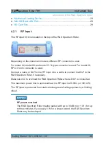
appropriate message. Thus, measurements without a valid reference can be avoi-
ded.
For more information on configuring the BNC connector for the appropriate signal,
see
"Configuring the BNC connector"
on page 49 and
4.2.3
Headphone Jack
The 3.5 mm connector for headphones is located on the top of the R&S Spectrum
Rider.
The internal impedance of the connector is approximately 10
Ω
.
4.2.4
USB Port
The two USB ports are located on top of the R&S Spectrum Rider.
You can use the USB interface to connect a memory stick and store data sets or
screenshots.
The USB connector can also be used to control the operation of the power sensor
and GPS receiver. See
Chapter 5.2, "Using a Power Sensor"
Chapter 4.7.3, "Using the GPS Receiver"
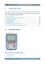
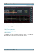
Connectors of the R&S Spectrum Rider


