


~.
,'¢'
.
!"~~~,:.:.
RAN
C 0
INS
TAL
L
'
.:r·
T'"
I ~0
N
INS
T
Ru
e
T ION
S
\
.
~:
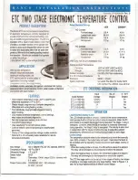
HC TWO ~
PROD
UCT DESC
CT
R
HI(
T
N
TROl
T
h
e
Ra
o
f
e
l
e
e
i
e
m~
~
b
UJ
e
CO
O
i
r
c
a
s
,
pr
o
vi
d
e o
n
/
o
ff con
tr
o
l
f
o
r
e
i
ng
,
ai
r
co
ndition
i
ng an
d
r
e
fr
i
ge
r
a
t
i
o
n.
T
h
e E
TC
i
s
equi
p
ped
with a
l
iqu
i
d crys
t
a
l
disp
l
a
y
(
LCD
)
t
h
a
t
provides a constan
t
reado
ut
o
f
t
he
sens
ed tem-
perature
,
and a touch keypad that allo
w
s
t
h
e u
s
er
t
o easily and a
cc
urately select the set point tem-
pe
r
a
t
ure
,
d
i
fferent
i
a
l
and heating/cooling
mode of
the operat
i
on.
Mod
e
ls a
r
e a
v
a
i
lable that op
e
rat
e
o
n
e
it
h
e
r l
i
n
e
vo
l
t
age
(
120
/
208
/
2
40 VAC
)
o
r
I
I
N
O
C
onta
c
t
F
ull-load amps
L
o
cke
d
rot
o
r amps
Resisti
v
e am
p
s
Ho
r
se
p
o
w
er
9.8 A
58.8A
9.8A
1/2 hp
4.9A
29
.
4 A
4
.
9A
1/
2 hp
.
8A
5.
8
A
1
/
4 hp
2
.
9 A
1
7
.
4
A
2.9A
1/4 hp
-
20
°
F
t
o
1
40
°
F (
-
29
O
C to 60
O
C)
-40
°
F
t
o 176
°
F (
-
40
O
C to 80
O
C)
o
to 95
%,
RH
,
Non
-
c
o
ndensing
!
m
pE
l
d
a
n
c
e
1
K
E
M
A
1
.
P
l
as
t
i
c
U
L
·
s
t
e
d
.
F
il
e
E
9
44
19
,
G
ui
de XA
P
X
CS
A
C
er
t
if
i
e
d
, Fi
l
e
L
R
6
8
3
40
,
Class
4
813 02
com
p
r
es
so
r c
o
n
tr
o
l,
tw
o s
t
age
h
ea
t
i
n
g
,
/
~
-
-
ven
t
ilation
con
t
rol, au
t
oma
t
ic changeov
er
,
c
o
nd
e
nser f
a
n
cyc
lin
g
,
space a
n
d
r
etu
rn
a
ir
tempe
r
at
u
re control
,
water coo
l
e
d
condensers
I
wi
th
a
l
a
rm f
u
n
t
i
o
n
.
FEATUR
E
S
•
W
i
de setp
o
i
n
t t
em
p
e
r
a
t
u
r
e
r
a
n
g
e (-3
0
°
F t
o 220
°
F) and
d
iffere
nti
al adjustmen
t
(
1
°
F
t
o 30
°
F
).
•
Simple keypad program
m
ing
o
f
setpoint temperature
,
differen
t
ial an
d
coolingl
h
eat
i
ng
modes.
•
Two individually p
r
ogra
m
mable
stages for hea
t
i
ng
and/o
r
coo
l
ing
.
•
LCD readout of sensor temper
a
ture
,
co
n
t
ro
l settings
,
r
elay status and onboard d
i
agnos
t
ic
s
.
•
Remote temperature sensing u
p to 400 fe
e
t
.
•
Two SPOT outpu
t
rela
y
s
.
•
Use
r
-se
l
ectab
l
e
Fa
hrenhe
i
t
/
Cels
i
u
s
s
ca
l
es
.
•
L
ocko
ut
s
wit
c
h to prevent tamperin
g by unauthorized
pe
r
son
n
el
.
•
C
h
o
i
ce of l
i
ne
v
ol
t
age a
n
d lo
w
voltage mode
l
s available.
•
Option
al
0
t
o 10
v
ol
t
analog out
p
ut av
ai
lable
f
o
r r
emo
t
e
tem
p
er
ature
indica
t
ion
.
I
np
u
t
N
o. of
0-10
V
C
o
d
e Num
ber
V
o
lt
age
S
t
ages
Output
E
T
C-2
1
1
000
-000
120/240
2
No
ET
C-2
11
1
00
-00
0
1
20/24
0
2
Ye
s
ET
C
-2120
00-00
0
2
4
2
N
o
ET
C·2
1
21 00-000
2
4
2
Y
es
120 or 208/240 VAC (24 VAC optional)
,
50/60 Hz
-30
°
F to 220
°
F
1
°
F
t
o 30
°
F
SPOT
Thermistor
,
1
.
94 in. long x 0.25 i
n. di
a
me
te
r
w
i
th
8
ft.
cable
120/208
/
240 VAC
: 1
00
mi
l
l
i
a
mp
s
24
VAC
:
2-6
VA
C
OPERATION
Li
quid Crystal
Display (LCD)
T
he L
C
D display p
r
ovides a c
ons
tant
r
e
ad
out o
f
the sensor temperature
a
nd i
n
dicates if either o
f
the
t
wo o
utp
u
t r
elays is energized
.
When
t
he
S1
an
nunciato
r
is constantly illuminated during ope
r
a
t
ion
, t
he Stage
1
relay is
e
ne
r
giz
ed
.
L
i
k
e
w
i
s
e
,
when th
e
S
2
annunciator
i
s constan
t
ly illumi
n
ated
d
uring
op
era
ti
on
,
th
e Stage 2
r
elay
i
s energized
.
The display is also
u
se
d
i
n
conjunc
t
ion
with the
k
e
y
pad to
a
l
l
ow t
he user to adjust the setpoint
t
emperatures
,
dif
f
ere
nt
ia
ls and heat
i
ng
/
cooling
modes for each stage
.
C
ontrol Setup
The tempe
r
ature setpoin
t r
e
f
e
rs t
o
the
t
emp
e
r
at
u
re
at which the normally
o
p
en (NO) co
n
tac
t
s
o
f
th
e
ou
t
put rela
y w
i
l
l
o
pen
.
D
e
te
r
m
i
ne the
l
oads to
be controlled a
n
d t
h
e ope
r
a
t
i
ng modes requ
i
r
ed
f
o
r
each stage
,
cooling or
h
eating.
•
W
hen the coolin
g
mode is c
h
o
s
e
n
,
the d
i
ff
e
r
e
nt
ial is above the setpoin
t
.
The relay will de
-
ene
r
gize as
t
he
tem
perat
u
re falls to
t
he setpoin
t
.
•
W
hen the heat
i
ng
m
ode is c
h
ose
n
,
th
e d
iffer
ent
i
al is below the setpoint
.
The
r
elay
w
i
l
l de
-
ener
gi
ze
a
s
th
e
t
e
mp
e
r
a
t
u
r
e
rises to the setpoin
t
.
The ETC two stage con
t
rol can be set
u
p
f
or t
w
o
st
ages of heating
,
two stages
of cooling or one stage cooling p
lu
s o
n
e s
t
age hea
t
i
n
g. Refer to Figures 1
,
2
and 3 for a visual represen
t
atio
n
s of different con
t
ro
l
se
t
ups.
Input Voltage
T
empe
r
at
u
re
Ra
n
ge
Differen
t
ial Range
Switch Ac
t
ion
Sensor