D8128D
OctoPOPIT Module
Installation Instructions
Page 1: ...D8128D OctoPOPIT Module Installation Instructions ...
Page 2: ...D8128D OctoPOPIT Module Installation Instructions 41343D Page 2 2001 Radionics ...
Page 3: ...trol Communicator Using Molex Connectors 13 3 4 Wiring OctoPOPIT Sensor Loops 14 3 4 1 D8128D OctoPOPIT Switch Settings for D9412 and D9112 14 3 4 2 D8128D OctoPOPIT Switch Settings for D7412 and D7212 15 3 4 3 D8128D OctoPOPIT Switch Settings for D9112B1 15 3 4 4 D8128D OctoPOPIT Switch Settings for D7212B1 15 Index 16 Figures Figure 1 D8128D OctoPOPIT Layout 9 Figure 2 Mounting Enclosure 10 Figu...
Page 4: ...D8128D Contents D8128D OctoPOPIT Module Installation Instructions 41343D Page 4 2001 Radionics Notes ...
Page 5: ... that you may use while programming your panel It may also indicate an important fact that should be noted Bold Italicized used to denote notes cautions and or warnings Italicized text used to reference the user to another part of this manual or another manual entirely It is also used to symbolize names for records that the user will create Courier Text indicates what may appear on the D5200 Progr...
Page 6: ...ire Initiation Applications You must use the D125B Powered Loop Interface Module or D129 Dual Class A initiation Circuit Module for fire initiation applications Connect the initiating devices smoke detectors for example to the D125B powered loops or D129 Class A loops Connect the zone outputs on the D125B or D129 to the OctoPOPIT sensor loop inputs The D125B or D129 and the OctoPOPIT must be mount...
Page 7: ... 2 Module Description The D8128D OctoPOPIT Module combines the functions of the D8125 POPEX module and the D8127 D9127 POPIT modules to provide eight off board points in a single module You can wire both D8128D OctoPOPIT and D8125 POPEX modules in parallel to the ZONEX Bus terminals on the same panel Review the Power Outputs section of your panel s Operation and Installation Manual to be sure you ...
Page 8: ...D8128D Overview D8128D OctoPOPIT Module Installation Instructions 41343D Page 8 2001 Radionics Notes ...
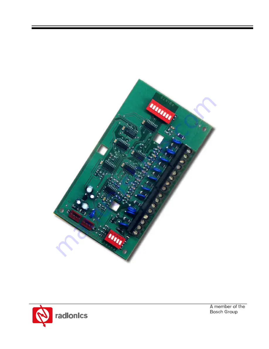
Page 9: ...ts depending on the control panel you are using 2 3 4 5 1 6 7 8 P O I N T S Molex Connectors Address Dipswitches Terminal Strip Point Dipswitches Figure 1 D8128D OctoPOPIT Layout 3 1 1 2 Line Termination Switch Settings Switch 5 sets line termination If there is no D8125 POPEX module connected to ZONEX 1 set switch 5 of only one D8128D connected to those terminals to the ON position If there is a ...
Page 10: ...ns in the enclosure See Figure 2 2 Use the screws provided with the module to secure it in the enclosure POINT CHART LABEL MOUNTING SKIRT HOOK MODULE MOUNTING LOCATIONS MODULE MOUNTING LOCATIONS TAMPER SWITCH MOUNTING LOCATION MOUNTING SKIRT HOOK SKIRT MOUNTING HOLE Figure 2 Mounting Enclosure 3 3 Wiring the OctoPOPIT Disconnect all power to the Control Panel before beginning any work with the int...
Page 11: ...connecting the D8128D to a D9412 D9112 D7412 or D7212 via the OctoPOPIT s terminal strip the following connections must be made D8128D D9412 D9112 D8128D D7412 D7212 Common Terminal 23 Common Terminal 9 Out Zonex 1 Terminal 27 In Terminal 28 Zonex 2 Terminal 25 Out Terminal 27 In Zonex 1 Terminal 28 12 V Terminal 3 Zonex 2 Terminal 26 12 V Terminal 24 Table 4 Terminal Strip Connections ...
Page 12: ... 73 127 ZONEX BUS 2 Switch 1 CLOSED Points 129 192 ZONEX BUS 2 Switch 1 OPEN Points 193 247 GND AUX IN OUT LOO D8125 POPEX D9127U ZONE EXPANSION LOOP DAT POSITIVE NEGATIVE Bus 1 Bus 1 continued Bus 2 continued Bus 2 P O I N T S P O I N T S P O I N T S 2 3 4 5 1 6 7 8 P O I N T S 2 3 4 5 1 6 7 8 2 3 4 5 1 6 7 8 P O I N T S 2 3 4 5 1 6 7 8 P O I N T S SENSOR LOOPS SENSOR LOOPS SENSOR LOOPS Figure 3 ...
Page 13: ... that the molex plug can only fit in one direction However to be sure the connector is attached correctly make sure the red wire is on the bottom of P1 or P2 and the black wire is on the top 28 27 26 25 24 23 TERMINAL 9 ON D7212 D7412 TERMINAL 3 ON D7212 D7412 COM IN OUT 12V P1 P2 Control Communicator D8128D Figure 4 Wiring the D8128D to the Panel using the Molex Connectors When connecting multipl...
Page 14: ...r are labeled COM Terminate each OctoPOPIT sensor loop with a 1 kΩ end of line resistor Attach a resistor even if you don t enable the loop The OctoPOPIT comes with a D105BL resistor for each sensor loop TO PANEL TO ADDITIONAL OCTOPOPIT SENSOR LOOPS OCTOPOPIT SENSOR LOOPS 1k EOL RESISTOR RPN D105BL COM IN OUT 12V P1 COM P2 P3 COM P4 P5 COM P6 P7 COM P8 D8128D OctoPOPIT Figure 6 D8128D OctoPOPIT Se...
Page 15: ...tches ZONEX 2 Points 9 72 1 2 3 4 5 Points 73 135 9 16 ON ON ON ON 73 80 17 24 ON ON ON OFF 81 88 25 32 ON ON OFF ON 89 96 33 40 ON ON OFF OFF 97 104 41 48 ON OFF ON ON 105 112 49 56 ON OFF ON OFF 113 120 57 64 ON OFF OFF ON 121 128 Refer to the table at right to set the OctoPOPIT switches for use with the D9112B1 Control Communicator Line Termination Switch see section 3 1 1 2 Line Termination Sw...
Page 16: ...Wiring the OctoPOPIT 10 Connecting to panel using Molex Connectors 13 Connecting to panel using Terminal Strip 11 L Listings UL 5 Central Station Burglary Alarm 5 Household Burglary Alarm 5 Local or Police Connected Burglary Alarm 5 M Module Description D8128D 7 Molex Connectors Connecting to panel 13 Mounting the OctoPOPIT 10 O OctoPOPIT Mounting 10 Wiring 10 Wiring Sensor Loops 14 S Setting Octo...