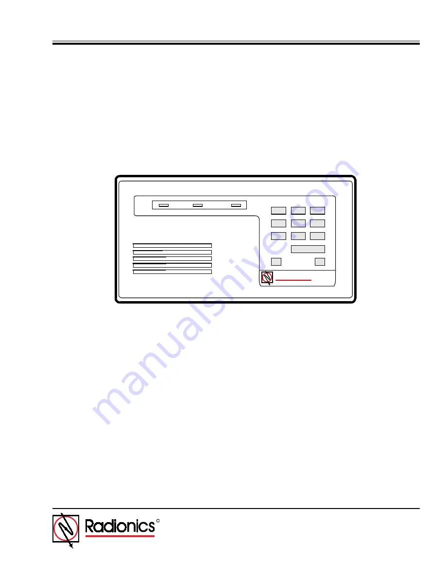
D279A
Independent Zone Control (I.Z.C.)
Operation and Installation Guide
R
DELAYED
INSTANT
ARMED
3
2
1
5
6
4
8
9
7
*
fi
Radionics
Page 1: ...D279A Independent Zone Control I Z C Operation and Installation Guide R DELAYED INSTANT ARMED 3 2 1 5 6 4 8 9 7 fi Radionics ...
Page 2: ...D279A Operation Installation Guide 46456B Page 2 Copyright 2000 Radionics D279A ...
Page 3: ...tput 11 4 8 Panic Alarm Function 11 4 9 Relay Output 11 4 10 Delayed LED 11 4 11 Instant LED 11 4 12 Armed LED 11 4 13 Buzzer 12 4 14 Lighted Keys 12 5 0 Programming 13 5 1 User Passcode 13 5 1 1 Recovering the Standard Passcode 13 5 1 2 Programming or Changing the Passcode 13 5 2 Programming the D8112 Panel Protective Zone 14 5 2 1 Supervised Independent Zone Controls Opening and Closing Reports ...
Page 4: ... Figure 1 Installing the D279A 9 Figure 2 Wiring the D279A 9 Figure 3 D279A Printed Circuit Assembly 13 Tables Table 1 D279A Independent Zone Control Operation and Installation Guide Organization 5 Table 2 Referenced Literature 5 Table 3 D279A Spefications 7 Table 4 Recommended D8112 Zone Codes 14 ...
Page 5: ...ture Radionics Part Number D4112 Installation and Programming Manual 73 05365 002 6112 Main Program Entry Guide 74 04367 000 8112 Main Program Entry Guide 74 03762 000 9000 Series Program Entry Guide 74 07695 000 Table 2 Referenced Literature 1 3 Documentation Conventions 1 3 1 Type Styles Used in this Manual We use special type styles to help you identify the objects that we are describing in thi...
Page 6: ...ns it may cause interference to radio and television reception It has been type tested and found to comply with the specifications in Sub part J of Part 15 of FCC rules for Class B Computing Devices If this equipment causes interference to radio or television reception which can be determined by turning the equipment on and off the installer is encouraged to correct the interference by one or more...
Page 7: ...t Requirements Keypad Idle 60 mA Keypad lighted buzzer on both loops faulted and relay activated 104 mA Auxiliary Relay Rating Form C contacts 12 VDC 2 A max Dimensions H x W x D 4 6 x 8 2 x 0 816 in 11 6 x 20 7 x 0 2 cm Wiring A 10 wire quick connect plug in cable is provided for interfacing the D279A with the Control Communicator and the protective loops 22 AWG 1 2 mm or heavier gauge wire requi...
Page 8: ...D279A Operation Installation Guide 46456B Page 8 Copyright 2000 Radionics D279A Overview Notes ...
Page 9: ...CHED Figure 1 Installing the D279A 1 Remove the front cover from the enclosure base see Figure 1 above Use a small flat blade screwdriver to gently push the two bottom cover tabs back As the tabs are pushed back lift the bottom of the cover away from the base Remove the cover Figure 2 Wiring the D279A Circled numbers represent terminals on control panel J4 JUMPER POSITION FOR SINGLE ZONE CONNECTIO...
Page 10: ...re PIN 10 is pointing toward the top Plug the connector into the back of the enclosure 4 Place the enclosure base on the wall in the desired location and mark the locations of the mounting holes The base can be mounted to a single gang wall box The two mounting screw holes in the base of the D279A are positioned for standard single gang compatibility Secure the enclosure base to the wall or gang b...
Page 11: ...ring the passcode arms and disarms the D279A 4 7 Burglary Alarm Output Opening or shorting the delayed or instant loop while the D279A is armed causes the output to short the panel zone after entry delay on delayed loop or point for a minimum of three seconds 4 8 Panic Alarm Function Simultaneously pressing both asterisk buttons shorts the Panic output and initiates an alarm Panic outputs from sev...
Page 12: ...arm occurs or the D279A is disarmed If you press a numbered key while the D279A is disarmed and a loop is faulted the buzzer indicates that the D279A is not ready to arm The D279A can only be armed if both loops are normal 4 14 Lighted Keys The D279A keys light during the entry delay period and when you press number keys or the command bar Operation ...
Page 13: ...If you make a mistake while programming restart the procedure from Step 2 If programming is not completed in 60 seconds the Independent Zone Control reverts to the old passcode As shipped the J3 jumper plug is placed across the top two pins which enables passcode change see Figure 3 The passcode change W1 J3 J4 CUT JUMPER W1 FOR D8112 OPENING AND CLOSING REPORTS IF PANIC BURGLAR OUTPUTS ARE CONNEC...
Page 14: ...nd closing reports are not transmitted from the zone controlled by the D279A Programming 5 2 3 Priority Zone Functions Programming the D279A as a priority zone enables two valuable functions When the zone code for the D279A is programmed with a 3 4 7 or 8 in the fourth digit position the IZC zone must be armed before the system can be master armed However once the D8112 is armed the D279A may be a...
Page 15: ...ripped while armed The D4112 or D6112 must be programmed with a bell time and the zone code must be programmed for audible alarms 5 5 Programming the D9112 for the D279A The D279A can be used in one of two ways with the D9112 The D279A controls arming disarming and entry exit delay for the point input it s connected to If the W1 jumper is cut point opening and closing reports may also be sent In t...
Page 16: ...rt SHORT The point is in Alarm when the D279A is armed and is in Trouble when the D279A is Disarmed This will allow supervision of the wiring between the D279A and the panel A D279A programmed for non priority does not affect the assigned area when armed See the 9000 Series Program Entry Guide 74 07695 000 for more information 5 6 2 Assigning the D279A to a Point with Index 18 The Point Response m...