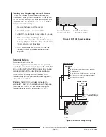
D2112/D2112E Installation Manual
Page 20
74-07111-000-D 196
© 1995 Radionics
System Wiring Diagram, Issue A
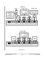
D2112
s
s
D126
Battery
12V 7Ah
P
P
P
P
S
D164 Phone
Cord to
RJ31X for
Phone Line
16 VAC
25 VA
60 HZ
Transformer
Required for
Fire and
Combined
Fire/Burglary.
Optional for
other.
Listed Audible
Signaling Device
Rated At 10.2
TO 13.9 VDC
(Do NOT Use
Vibrating Type
Horns)
-
-
+
+
D1240
Battery
12V 4Ah
P
D1625
D8004
Transformer
Enclosure
S
P
P
D133
Relay
P
D133
Relay
P
P
Supervised with 1k
Ω
EOL Resistor.
Typical Initiating
Devices are Door
Contacts NO/NC,
Floor Mats, Motion
Sensors, Glass Break
Detectors, etc.
NOT Supervised,
Normally Closed.
Typical Initiating
Devices are Door
Contacts, Floor
Mats, Motion
Sensors, Tamper
Switches, etc. All
devices open on
alarm.
P
S
Supervised
with 6.8k
Ω
EOL Resistor.
P
S
P
S
P
S
P
S
P
S
P
P
Arming Station
D202
Up to
Four
D2112E
P
S
P
S
P
S
D126
Battery
12V 7Ah
P
P
P
P
S
16 VAC
25 VA
60 HZ
Transformer
-
-
+
+
D1240
Battery
12V 4Ah
D1625
S
P
P
D133
Relay
P
D133
Relay
P
P
P
S
P
S
P
S
P
Listed Audible
Signaling Device
Rated At 10.2
TO 13.9 VDC
(Do NOT Use
Vibrating Type
Horns)
Required for
Fire and
Combined
Fire/Burglary.
Optional for
other.
D164 Phone
Cord to
RJ31X for
Phone Line
Supervised with 1k
Ω
EOL Resistor.
Typical Initiating
Devices are Door
Contacts NO/NC,
Floor Mats, Motion
Sensors, Glass Break
Detectors, etc.
NOT
USED
NOT
USED
Aux Power Fuse
2 Amp Fast Blow
Alarm Output Fuse
2 Amp Fast Blow
Arming Station
D202
Up to
Four
D8004
Transformer
Enclosure
1
2
3
4
5
6
7
8
9
10
11 12 13 14
15
16 17
18
19 20
21
22 23
24
25 26 27 28 29
1
2
3
4
5
6
7
8
9
10
11 12
14
15
16 17
18
19 20
21
22
26 27 28 29
23 24 25
13
P
S
= POWER LIMITED
= SUPERVISED
P
S
= POWER LIMITED
= SUPERVISED
2.0k


