background image

Quick Start - RE400

6/1/2010

1. The first start of radio modem

Don’t connect radio modem in your LAN before settings! Default IP address of radio modem may
be already used in your network.

Do not switch on more than one radio with default settings at any one time! Only switch on the next
one after setting and storing IP parameters in the first one.

Interconnect ETH connector of radio modem with your PC using standard cable.

Switch on power (PoE or AUX). PWR and ETH LED have to light. After 20 sec. STATUS starts to
blink in green.

Set IP and mask of your PC to 192.168.1.233, mask 255.255.255.0 (check user manual).

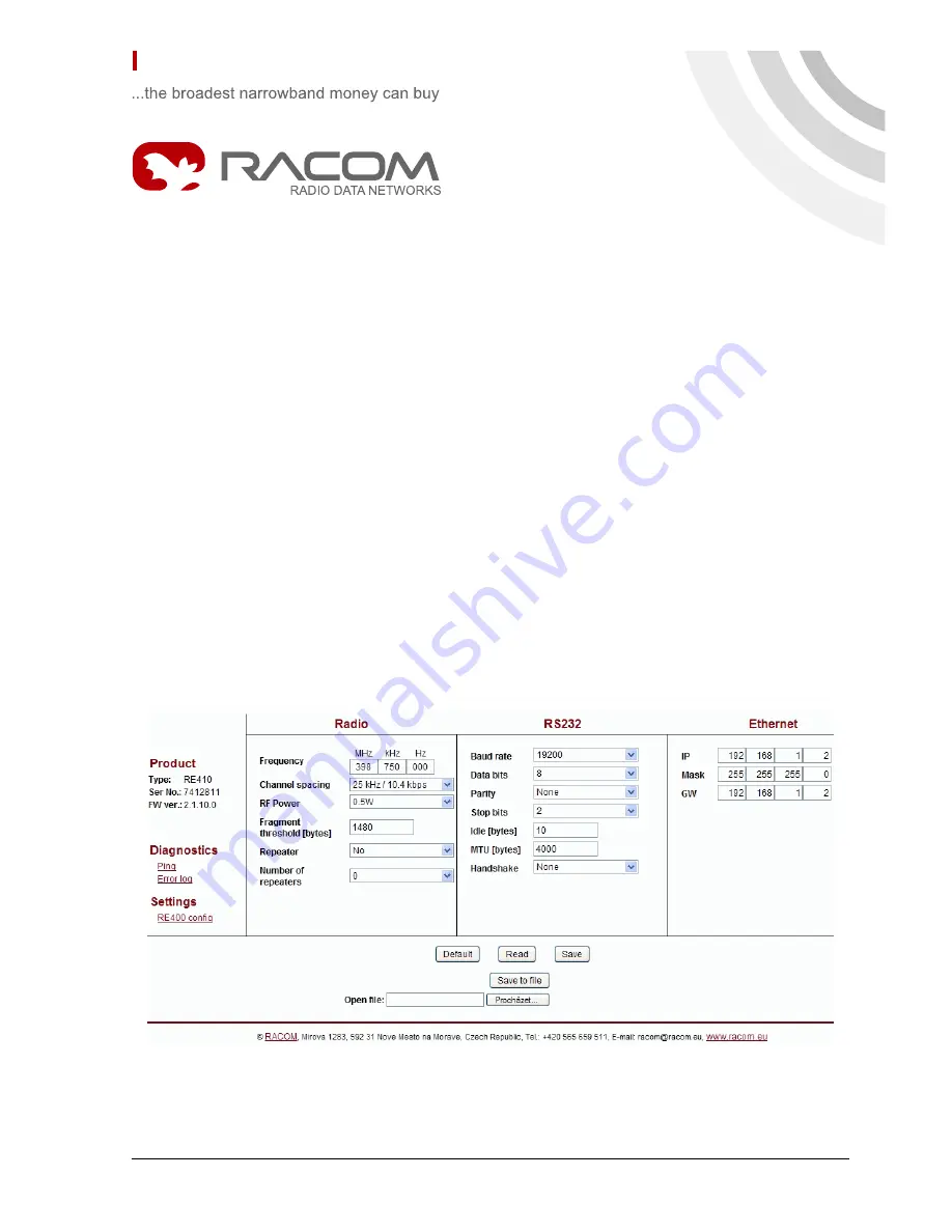
Start www browser on address 192.168.1.2.

Set radio modem configuration and Save it.

Select a unique IP address of each radio modem within the network.

When IP address is changed, conection with radio modem is lost. Next communication is possible
after change of IP address in www browser, possibly in your PC.

1

© RACOM s.r.o. – Quick Start - RE400

Summary of Contents for ECONOMY RE400

Page 1: ...or of radio modem with your PC using standard cable Switch on power PoE or AUX PWR and ETH LED have to light After 20 sec STATUS starts to blink in green Set IP and mask of your PC to 192 168 1 233 mask 255 255 255 0 check user manual Start www browser on address 192 168 1 2 Set radio modem configuration and Save it Select a unique IP address of each radio modem within the network When IP address ...

Page 2: ...2 RS232 DSUB9 female Tab 1 RS232 DSUB9F pins signal pin signal pin DSR 6 CD 1 RTS 7 RxD 2 CTS 8 TxD 3 PWR 9 DTR 4 GND 5 2 3 Ethernet interface Fig 3 RJ 45F Ethernet connector RJ 45 for 10BaseT and 100BaseT meets fully standard of Power over Etrhernet IEEE802 3af Radio modem recognizes standard or cross cable and adapts itself automatically 2 4 Power suply possibilities AUX via RS232 DSUB9 connecto...

Page 3: ...with 100 Mb s speed Yellow blinking data transfer with speed of 100 Mb s Green connected with 10 Mb s speed Green blinking data transfer with speed of 10 Mb s 232 Green data receiving Yellow data transmitting STATUS status of operating system Green blinking with period 2 sec ON 1 sec OFF main mod Yellow blinking with period 1 sec ON 1 sec OFF Service mode Yellow blinking with period 0 2 sec ON 0 2...

Page 4: ...z channel Data rate in RF channel 5 2 kbps in 12 5 kHz channel 10 4 kbps in 25 kHz channel Ethernet RS232 Interfaces SMA Antenna connector 100 000 hodin MTBF Mean Time Between Failures PoE AUX Power method 38 57 V 10 8 30 V nomin 13 8 V Power supply 145 mA 48 V 430 mA 13 8 V Idle state Rx Power consumption cca 230 mA 48 V 700 mA 13 8 V Low power Tx 310 mA 48 V 950 mA 13 8 V High power Tx 25 až 55 ...

Reviews: