


GRB-200 Demodulator (GOES-R) OI&M
GRB-200 Demodulator (GOES-R) OI&M
© Copyright 2015, Quorum Communications, Inc.
Revision A.01
44
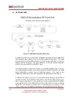
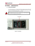
4.1 RF FRONT END
Figure 32 - GRB-200 Demodulator RF Section
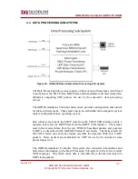
The RF Front End received the LHCP and RHCP IF signals from the GRB Feed
and conditions these signals for use by the Demodulator Sub-system. The signal
processing for the LH and RH channels is in most respects identical, so only one
channel will be discussed. The only difference is that the antenna alignment
signal is only generated from the RHCP input.
The incoming signal is filtered by means of a 140 MHz bandpass filter to remove
out-of-band signals and also by a narrow band SAW filter matched to the GRB
signal bandwidth to remove close-in interfering signals. The signal is also
amplified to match the level to that required by the Demodulator Sub-system.
In addition, the signal is passed to a log amplifier and an analog-to-digital (ADC)
converter to allow the Controller Sub-system to read the incoming signal levels.
ADC voltage representative of the signal level is also generated from the RHCP
input and provided to the GRB Feed over the control cable to assist in antenna
alignment. An increase in signal level is represented by an increase in DC
voltage. Please see the GRB Feed manual for more information on the function.