background image

MedTrack CR60 Rehabilitation Treadmill Service Manual

Repair/Replacement and Calibration   4-3

Tachometer

Wooden blocks

Belt-tension calipers (optional) 

Masking tape or heavy pencil

Although some procedures are used for several applications (removing the 
hood, for example), each procedure is explained only once. Reference 
procedures under their headings for subsequent applications. 

All references to front, rear, left, and right are given as though you were 
facing the front handrail while walking on the deck.

Removing the Treadmill Hood

1. For your convenience in working, elevate the treadmill to its 

maximum height, if possible.

2. Turn off the circuit breaker on the treadmill hood, then unplug the 

treadmill from the power outlets. 

Warning!

To prevent high voltage electrical shock, wait at least two 

minutes from the time you unplug the power cords before 

working on or around any electrical or mechanical 

component under the hood.

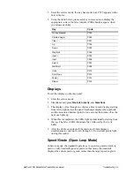
3. Remove the four Phillips-head screws from the configuration plate. 

4. Remove the three ¼-20 Phillips-head screws located under the label 

panel on the front of the hood.

Configuration
Plate

Screw - #10-32 c 0.375L 

Hood screws

1/4-20 x 0.50L 

Ext. Star Lock Washer 

Lock Washer - ext. star #10 

Summary of Contents for MedTrack CR60

Page 1: ...MedTrack CR60 Rehabilitation Treadmill Service Manual P N 042101 001 Rev A...

Page 2: ...and MedTrack are trademarks or registered trademarks of Quinton Cardiology Inc All other product and company names are trademarks or registered trademarks of their respective companies 1995 1997 2004...

Page 3: ...written for Quinton authorized service personnel with proper training There are no user serviceable parts in the treadmills Any attempt by non Quinton trained personnel to service the treadmill can v...

Page 4: ......

Page 5: ...r Assembly 2 2 Controller Assembly 2 2 Key Panel 2 2 User Inputs 2 2 Output Displays 2 3 Additional Functions 2 3 Controller to Treadmill Interface 2 3 Headframe Assembly 2 3 Input Power Module 2 3 Dr...

Page 6: ...ion Plate 4 5 Field Functional Test 4 5 Replacing the Power Cord 4 6 Hard wired Cords Low Voltage Units 4 6 Detachable Cords High Voltage Units 4 6 Field Functional Test 4 6 Replacing the AC Drive Mod...

Page 7: ...pers 4 23 Walking Belt Tracking 4 24 Controller Assembly 4 24 Removing the Enclosure 4 25 Field Functional Test 4 25 Replacing the PCBA 4 25 Configuring the Controller 4 26 Field Functional Test 4 26...

Page 8: ...ield Functional Tests Complete Field Functional Test D 1 Test A Test the Controller Displays D 1 Test B Test the Multi Display D 2 Test C Test the Controller Operation D 2 Test the Controller Keys D 2...

Page 9: ...CR60 Rehabilitation Treadmill Service Manual Introduction 1 1 1 Introduction Overview The MedTrack CR60 Rehabilitation Treadmill with a built in controller is designed for rehabilitation exercise Fro...

Page 10: ...appropriate dedicated electrical circuit Nothing else should be connected to the circuit Operation The controller is a computerized panel used to operate the treadmill It is mounted above the front ha...

Page 11: ...rface It is mechanically attached to the deck The user presses a key on the controller to enter a command The controller processes the user entered information displays all exercise data and sends com...

Page 12: ...ive roller pulley Controller Assembly The controller assembly consists of a key panel and PCBA mounted in an enclosure The enclosure which has a removable rear panel mounts to the uprights Controller...

Page 13: ...er from the treadmill drive board as the power source for all circuitry and for the LED displays Headframe Assembly The headframe assembly consists of the following components Input power module Drive...

Page 14: ...e grade pinion shaft using a chain and a set of speed reduction sprockets The grade pinion shaft in turn drives a set of rack gears which raise and lower the front of the treadmill A grade potentiomet...

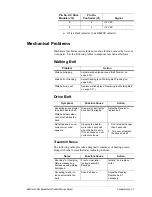
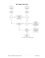
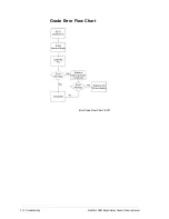
Page 15: ...al Problems Noise Vibration Grade Speed Belts Use the tables and flow charts on the following pages to diagnose problems See Chapter 4 for repair and replacement procedures Tools The following tools m...

Page 16: ...le the control remove magnet then press and Power simultaneously Circuit breaker on treadmill set to OFF Set treadmill circuit breaker to ON Building circuit breaker tripped Contact building maintenan...

Page 17: ...or crimp as required Replace configuration plate Treadmill stops during run but Stop Belt button has not been pressed No error message appears Look for loose ground wires Reconnect and secure if loose...

Page 18: ...wer electronics 5 Power electronic component failure 6 Motor block by obstruction 1 Restrict use to people within the weight speed specifications 2 Check deck wear replace if necessary 3 If the motor...

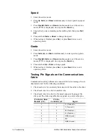
Page 19: ...ssociated decimal point for one second then turns off as the next one lights up 4 When this is completed the LEDs light up individually starting from the top The Select LEDs illuminate first followed...

Page 20: ...3 Press Stop Belt Faster and Slower simultaneously to exit the service mode P5555 is displayed do not press the Power key 4 Press and hold Up or Down to change grade 5 When testing is finished press...

Page 21: ...ee Walking Belt Tracking on page 4 24 Walk belt worn out Replace walk belt see Replacing the Walking Belt on page 4 21 Symptom Possible Cause Action Squealing sound similar to automobile fan belt Walk...

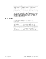
Page 22: ...near the suspected bearing and the other end near your ear Compare several bearings to determine which is the faulty one Flow Charts Use the flow charts on the following pages for step by step troubl...

Page 23: ...MedTrack CR60 Rehabilitation Treadmill Service Manual Troubleshooting 3 9 Bus Voltage Flow Chart Error Code Flow Chart EPHI and EPLO...

Page 24: ...3 10 Troubleshooting MedTrack CR60 Rehabilitation Treadmill Service Manual Grade Error Flow Chart Error Code Flow Chart E201...

Page 25: ...readmill Service Manual Troubleshooting 3 11 Drive Motor Error Flow Chart Error Code Flow Chart E203 Troubleshooting chart for all drive motor related error codes and failures Source power and power t...

Page 26: ...3 12 Troubleshooting MedTrack CR60 Rehabilitation Treadmill Service Manual Communications Link Error Code Flow Chart E204...

Page 27: ...MedTrack CR60 Rehabilitation Treadmill Service Manual Troubleshooting 3 13 Grade Problems Flow Chart...

Page 28: ......

Page 29: ...sted in Appendix A and the cautions and warnings printed below Use this manual only for servicing the MedTrack CR60 treadmill Do not use this manual for servicing other Quinton treadmills Electrical S...

Page 30: ...ak loose during service or operation Keep fingers away from rotating parts To avoid eye contaminants clean away dust and debris from moving parts before servicing Beware of sharp edges when replacing...

Page 31: ...k Removing the Treadmill Hood 1 For your convenience in working elevate the treadmill to its maximum height if possible 2 Turn off the circuit breaker on the treadmill hood then unplug the treadmill f...

Page 32: ...ont of the siderails Loosen the two rear screws holding the back part of the hood to the headframe CE units Remove the 10 screws that hold the hood to the uprights 8 Gently tap the hood a half inch to...

Page 33: ...e The screws are located in the center of the headframe protective ground is represented by the ground symbol shown to the left Be sure to rewire correctly 3 Unplug the wires from the drive board on t...

Page 34: ...uired replace the treadmill hood as described in step 10 page 4 5 Detachable Cords High Voltage Units Unplug the power cord from the connector on the configuration plate and plug in the new cord Field...

Page 35: ...me 5 Unplug the limit switch wires 6 Unplug the drive motor wires 7 Unplug the configuration plate wires 8 Remove the four Phillips screws securing the AC Drive Module 9 Remove the AC Drive Module and...

Page 36: ...me 5 Use either a 15 16 inch open end wrench or a large adjustable wrench to turn the large nut on the tensioner counter clockwise put tension on the poly V belt until the two lines on the tensioner l...

Page 37: ...g a large screwdriver or punch tap the retainer down above each bolt to secure the shaft 12 Assemble the treadmill following steps 1 6 in reverse order 13 Tension the drive belt as described on page 4...

Page 38: ...he front roller drive pulley to align the outside face of the motor drive pulley to within 0 020 inch Tighten the setscrews 10 Replace the poly V drive belt as described in Replacing the Poly V Drive...

Page 39: ...l Test To verify that the treadmill is operating properly perform Field Test No 2 on page D 5 Replacing the Grade Motor Place a clean sheet of cardboard or a clean rag on the treadmill deck before sta...

Page 40: ...lign the motor sprocket with the pinion shaft chain sprocket 7 Restore power to the treadmill and test the new grade motor Warning High voltage is present when the treadmill is plugged into a power so...

Page 41: ...chain If the link is inaccessible you will have to remove the motor See Replacing the Grade Motor on page 4 11 4 Slide out the master link 5 Install the new chain aligning it correctly on the sprocket...

Page 42: ...escribed on page 4 28 9 If no other service is required replace the treadmill hood as described in step 10 page 4 5 Grade Pot Wires At the end of each grade pot wire is a pin with a small metal flange...

Page 43: ...Restore power to the treadmill and decrease the grade until the wheels are approximately half inch above the floor 5 Remove the two hex head bolts holding the wheels to the rack gears Note the arrang...

Page 44: ...the headframe 1 Restore power to the treadmill 2 Enter open loop grade mode as described above 3 Insert rack gears into headframe 4 Decrease the grade until the gears bounce two or three times then in...

Page 45: ...Carefully lower the upright assembly onto the walk deck c Disconnect the controller cable and the ground wire from the drive board d Use a 3 16 in Allen wrench to remove both pivot bolts from the two...

Page 46: ...p 10 page 4 5 Field Functional Test To verify that the treadmill is operating properly perform Field Test No 4 on page D 5 Replacing the Pinion Shaft 1 Remove the power cords and treadmill hood as des...

Page 47: ...perly perform Field Test No 4 on page D 5 Adjusting the Grade Limit Switches Grade limit switches prevent the treadmill from exceeding the preset maximum grade When a roller on the limit switch reache...

Page 48: ...Remove optional siderails 2 Remove the poly V drive belt as previously described in Replacing the Poly V Drive Belt on page 4 8 3 Remove the end caps from both sides of the belt at the rear of the wal...

Page 49: ...xercising on the treadmill 1 Lower the treadmill to zero grade 2 Remove the power cords and treadmill hood as described in Removing the Treadmill Hood on page 4 3 3 Remove the front and rear rollers a...

Page 50: ...five long mounts and four short mounts on each siderail The front two mounts are attached with hex nuts underneath 3 Unscrew the mounts from each siderail and replace 4 Replace the deck as described...

Page 51: ...out of the belt with your fingers then grasp the belt with the second clamp 5 Repeat steps 3 and 4 on the other side of the belt using the other caliper 6 Set the dials of both calipers to zero 7 Alt...

Page 52: ...et it run for at least one minute at minimum speed and grade 2 Make the following adjustment to the right adjustment screw only a If the belt moves to the right turn the screw turn clockwise b If the...

Page 53: ...ler cable located on the left side of the PCBA 7 Remove the hex nut that holds the ground wires to the chassis then remove the wire 8 Cut the cable tie that holds the cable to the controller 9 Use a 5...

Page 54: ...g steps to configure the treadmill 1 Enter the service mode by simultaneously pressing Stop Belt Slower and Faster 2 Choose the appropriate configuration number from the following 3 Hold down Stop Bel...

Page 55: ...time of use for each treadmill This data can be useful for scheduling service The cumulative time and distance are stored in the controller Both values are zero if a new controller is installed Loadin...

Page 56: ...ood as described on page 4 3 2 Loosen the setscrew that holds the grade pot gear to the grade pot shaft 3 Restore power to the treadmill WARNING Maintain caution when working near moving parts 4 Enter...

Page 57: ...way to the top of the rack gear when the display reads 15 11 Turn off the power and disconnect the power cord from the power outlet 12 If no other service is required replace the treadmill hood as des...

Page 58: ......

Page 59: ...on the treadmill belt when it is started Recommended Service Routine service is necessary every six 6 months When service is required repairs can be done to the modular level Routine Maintenance Visu...

Page 60: ...shed procedure Do not use liquids on the deck surface Vacuuming Under the Treadmill Hood Dust and dirt beneath the hood can restrict the air flow needed to cool the unit and dissipate heat from the dr...

Page 61: ...readmill Hood on page 4 3 2 Vacuum the areas behind the AC Drive Module Do not vacuum the drive board 3 Replace the hood Replacement Schedules Replace belts if they are frayed or show excessive wear E...

Page 62: ......

Page 63: ...es that meet specifications as noted in this service manual Use of accessories or cables other than those specified with the exception of accessories or cables sold by Quinton Cardiology Inc as replac...

Page 64: ...ill belt Never place chairs or other objects on treadmills Keep the area underneath and around the treadmill clear Make sure cables are clear of the treadmill Be aware of a moving treadmill belt Allow...

Page 65: ...idance RF emissions CISPR 11 Group 1 The Medtrack Rehabilitation Treadmills use RF energy only for its internal function Therefore its RF emissions are very low and are not likely to cause any interfe...

Page 66: ...00 4 5 1 kV differential mode 2 kV common mode 1 kV differential mode 2 kV common mode Mains power quality should be that of a typical commercial or hospital environment Voltage dips short interruptio...

Page 67: ...mitters as determined by an electromagnetic site surveya should be less than the compliance level in each frequency rangeb Interference may occur in the vicinity of equipment marked with the following...

Page 68: ...cations equipment Rated maximum output power of transmitter W Separation distance according to frequency of transmitter m 150 kHz to 80 MHz 80 MHz to 800 MHz 800 MHz to 2 5 GHz 0 01 0 12 0 12 0 23 0 1...

Page 69: ...ction when present On power connected to mains Type BF equipment contains an F type isolated patient applied part providing a high degree of protection against electric shock Alternating current Type...

Page 70: ......

Page 71: ...0 6 to 7 2 mph 1 0 to 11 6 km h or 1 0 to 12 0 mph 1 6 to 19 3 km h Grade range 0 to 15 0 5 Rate of grade range 0 to 15 in 60 secs max with 400 lb user Physical Weight 400 lb 181 4 kg Nominal Walking...

Page 72: ...voltage range is listed on the serial number name plate which can be found on the hood under the circuit breaker switch Full load current is computed as described in section 430 24 of the National Ele...

Page 73: ...per second for the first three seconds five per second thereafter until you either release the key or reach the high low limit Accuracy Within 0 5 grade during unchanging operation MULTI FUNCTION DIS...

Page 74: ...ate option Units beats per minute Range 50 225 Increment 1 Scan Cycles through parameters displaying each sequentially for 3 sec Weight Default 150 lb or 68 kg Minimum 30 lb or 13 kg Maximum 400 lb 18...

Page 75: ...the spare part numbers by category Item Part Number ELECTRICAL Power Cord Low Voltage High Voltage 030610 004 030736 042 Strain Relief Low Voltage High Voltage 001227 011 031453 011 Configuration Pla...

Page 76: ...riple Flex Maintenance Kit 033511 001 End Cap Front Left 019306 001 End Cap Front Right 019306 002 End Cap Rear Left 019057 002 End Cap Rear Right 019058 002 Left Handrail Kit 030005 004 Right Handrai...

Page 77: ...for CE marked units ONLY 15 033316 002 SPARE MOTOR ASSEMBLY GRADE 16 032524 002 MODIFIED RACK GEAR 17 033171 002 SPARE ASSY GRADE POT 18 042153 001 SPARE AC DRIVE MODULE 19 037098 001 DRIVE MOTOR AC...

Page 78: ...C 4 Part Numbers MedTrack CR60 Rehabilitation Treadmill Service Manual 13 18 27 27 26 26 26 15 15...

Page 79: ...MedTrack CR60 Rehabilitation Treadmill Service Manual Part Numbers C 5 4 18 17 15 25 24 13 21 23 19 5 30 32 12 31 5 28 5 29...

Page 80: ......

Page 81: ...pter 4 Repair Replacement and Calibration Please read the entire chapter before starting The appropriate test must be performed as verification whenever any of the procedures in Chapter 4 are used Com...

Page 82: ...d do not go blank ESD static Make sure control panel is properly grounded Check the following All star washers are installed Green wire goes to drive board on AC Drive Module Continuity to ground on p...

Page 83: ...D Test the Grade Operation 1 Remove the power cords and treadmill hood as described in Removing the Treadmill Hood on page 4 3 2 Ensure the controller displays 0 0 grade 3 Measure the distance from t...

Page 84: ...sh away from the handrail The belt should begin rotating with little forward pressure and continue to rotate for several steps If additional pressure is required to keep the belt moving replace the be...

Page 85: ...e Grade Operation on page D 3 Test E Test Speed Operation on page D 3 Test H Shut Down the Treadmill on page D 4 Field Test No 3 The following steps must be performed with the treadmill completely ass...

Page 86: ...The following steps must be performed with the treadmill completely assembled except as noted With the power cord connected to the correct outlet turn on the circuit breaker Perform the following test...

Page 87: ...Manual Drawings E 1 E Drawings Wiring Diagrams These wiring diagrams for both the low voltage and high voltage treadmill models are shown as follows Wiring Diagram Low Voltage Treadmill on page E 3 Wi...

Page 88: ......

Page 89: ...E 3 Assembly Drawings Cardiac Stress Treadmills Service Manual Wiring Diagram Low Voltage Treadmill...

Page 90: ...E 4 Assembly Drawings Cardiac Stress Treadmills Service Manual Wiring Diagram High Voltage Treadmill...

Page 91: ...dicated line A 1 Distance cumulative use 4 27 Drive board 2 3 Drive motor assembly 2 4 Drive motor replacing 4 9 E Electrical problems 3 2 Electronic problems 3 3 Error codes 3 3 F Field test No 2 D 5...

Page 92: ...ve motor 4 9 grade motor 4 11 grade motor chain 4 13 grade potentiometer 4 13 PCBA 4 25 pinion shaft 4 18 poly V drive belt 4 8 power cord 4 6 rollers 4 20 tensioner 4 7 transformer 4 10 walking belt...

Reviews: