background image

33

EN

CHC1203 IT EN FR - REV001A

SYSTEM ERRORS

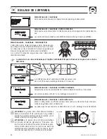
CAN BUS communication error

This fault is displayed if there are errors that cannot be recovered during CAN network 
communication. 
Make sure the data cables are properly connected.  

No MASTER 

This fault is displayed if there is not a chain counter with MASTER priority in the CAN net-
work (see chapter MULTIPLE CHAIN COUNTERS). 
See if the MASTER chain counter is on and the data line connections. 

SPEED

0M/M

LOW VOLTAGE

SPEED

0M/M

NO MASTER

SPEED

0M/M

CAN ERROR

SYSTEM FAULTS

System faults that appear on the state line divided into three categories which are shown below: problems with automat-
ic reset, problems with automatic reset and keys locked and problems with manual reset.

PROBLEMS WITH AUTOMATIC RESET

These faults are automatically reset as soon as the cause that had generated the problem disappears.  

Low voltage

The fault is displayed if the power supply voltage drops below 10.5Vdc for more than one 
second. The reset of this problem occurs if the power supply voltage exceeds the thresh-
old of 11.0Vdc for more than one second. 
Check the charge state of the battery group that supplies power or the electrical plant.

Opposed commands

This fault is displayed if keys UP or DOWN of the chain counter are pressed at the same 
time as the respective external control DOWN or UP key (another chain counter or 
another remote switch).
If the fault is present, keys 

p

,

q

 (UP, DOWN) are disabled.

PROBLEMS WITH AUTOMATIC RESET AND KEYS LOCKED 

These faults are automatically reset as soon as the cause that had generated the problem disappears. Some keys are dis-
abled when these faults are present.

Remote programming active

This fault is displayed if a chain counter has entered the SETTINGS menu in the CAN 
network (see chapter MULTIPLE CHAIN COUNTERS). Wait until the chain counter has exit 
the menu.
If the fault is present, key 

=

 (SELECT) is disabled.

SPEED

0M/M

OPPOSED

SPEED

0M/M

REMOTE PROG


Summary of Contents for CHC1203

Page 1: ...SALITA VELOCITA 20M M CHAIN COUNTER CHC1203 Manuale d uso CONTA CATENA CHC1203 User s Manual CHAIN COUNTER CHC1203 Manuel de l utilisateur COMPTEUR DE CHA NE CHC1203 High Quality Nautical Equipment I...

Page 2: ...2 CHC1203 IT EN FR REV001A...

Page 3: ...dow Pag 26 CHAIN COUNTER OPERATION Windlass electric drive Monitoring Pag 27 SETTING THE CHAIN COUNTER The structure of the menus Pag 28 SETTING THE CHAIN COUNTER Settings menu Counter reset Functions...

Page 4: ...sto dispositivo stato progettato e realizzato per essere utilizzato su imbarcazioni da diporto Non consentito un utilizzo differente senza autorizzazione scritta da parte della societ Quick Lo strumen...

Page 5: ...llante adatto per materiali metallici resistente all ambiente salmastro e in grado di sopportare temperature da 30 a 80 C tipicamente rispondono a questi requisiti alcuni collanti epossidici bi compon...

Page 6: ...e le proprie prestazioni e quelle degli strumenti posti nelle vicinanze Per questo motivo lo strumento deve essere distante almeno 25 cm dalla bussola 50 cm da un qualsiasi apparecchio radio ricevente...

Page 7: ...spegnere l apparecchio posizionare l interruttore in modo che sia facilmen te raggiungibile nel caso in cui sia necessario spegnere l apparecchio per evitare situazioni di pericolo Inserire un fusibil...

Page 8: ...ifica effettuata sul MA STER che provveder ad aggiornare automaticamente tutti gli strumenti SLAVE esclusi i men IMPOSTAZ PERS CON TROLLI e CONFIG CAN che contengono parametri e funzioni particolari p...

Page 9: ...ccia tra l utente e lo strumento avviene grazie a tre elementi IL DISPLAY GRAFICO LA PULSANTIERA E L AVVISATORE ACUSTICO BUZZER Sul display grafico sar visualizzata la misura della catena calata lo st...

Page 10: ...rte situazioni pu essere necessario calare l ancora sfruttando la possibilit del salpa ancora di fare scendere l ancora per gravit senza comando elettrico Anche in questa si tuazione lo strumento cont...

Page 11: ...AUTOM CONTROLLI CONFIG CAN USCITA ALLARM SALITA DISCESA AUTO CONTRASTO ILLUMINAZIONE TEMPO ILLUMINA SUONO TASTI ENGLISH ITALIANO FRANCAIS DEUTSCH ESPANOL UNIT MISURA GIRO BARBOTIN NUMERO MAGNETI TEST...

Page 12: ...atena non in grado compensare l inerzia meccanica del salpa ancora il bar botin pu ruotare nel senso della salita immediatamente dopo la disattivazione del comando Considerare questo fattore nella sce...

Page 13: ...nazione del display Il ritardo ha inizio a partire dal rilascio dell ultimo pulsante o dal termine della CADUTA LIBERA ILLUMINAZIONE IMPOSTA VALORE 4 TEMPO ILLUMINA IMPOSTA VALORE 30S I valori selezio...

Page 14: ...ro di magneti installati sul barbotin NUMERO MAGNETI IMPOSTA VALORE GIRO BARBOTIN IMPOSTA VALORE I valori selezionabili sono da 1 a 16 impostazione di fabbrica 1 Se l unit di misura impostata METRI i...

Page 15: ...ERO MAGNETI 1 GIRO BARBOTIN inc 240 numero di giri contati NUMERO MAGNETI 1 Dopodich sar mostrata per due secondi la seguente finestra e si ritorner al men IMPOSTAZIONI CALIBRAZ AUTOM FINE PROCEDURA M...

Page 16: ...opzione permette definire la priorit dello strumento sulla rete CAN vedi capito lo STRUMENTI MULTIPLI CONTROL FLASH CONTROL FLASH XXXX VERO YYYY SOMMA CONTROL EEPROM CONTROL EEPROM XXXX VERO YYYY SOM...

Page 17: ...iciente Il problema segnalato se la tensione di alimentazione scende al di sotto di 10 5Vdc per pi di un secondo Il reset del problema avviene se la tensione di alimentazione supera la soglia di 11 0V...

Page 18: ...CT o spegnimento e riaccensione dello strumento In presenza del problema i pulsanti p e q UP DOWN sono disattivati VELOCITA 0M M ALLARM SALITA VELOCITA 0M M MANCA SENSORE VELOCITA 0M M SENSOR GUASTO M...

Page 19: ...ATTERISTICHE AMBIENTALI Temperatura operativa 4 da 20 a 70 C Grado di protezione IP 67 CARATTERISTICHE GENERALI Interfaccia di comunicazione CAN bus con transceiver differenziale Connessioni esterne M...

Page 20: ...an lan guage reference will be made to the Italian or English text This device was designed and constructed for use on recreational crafts Other forms of use are not permitted without written authoriz...

Page 21: ...or metals resistant to brackish ambients and capable of withstanding temperatures ranging from 30 to 80 C Generally speaking some epoxy based bi component glues satisfy these requirements Several magn...

Page 22: ...its performance or interfere with operation of instruments found near it For this reason the chain counter must be at least 25 cm away from the compass 50 cm away from any radio receivers 1 m away fr...

Page 23: ...rn on and shut off the chain counter make sure the switch is in a position that can be easily reached so that in the event of an emergency the chain counter can be quickly shut off Install a 4A fast f...

Page 24: ...hain counter that will automatically update all the SLAVE chain counters except for menu PERSONAL SET UTILITY and CAN CONFIG that cointain particular functions and parameters for every single chain co...

Page 25: ...oyed between user and counter interface A GRAPHIC DISPLAY CONTROL KEYS AND BUZZER The graphic display screen shows the measure of chain lowered state of the chain counter along with other information...

Page 26: ...ce from another chain counter or other control or by shutting off the chain counter Free fall At times the anchor may have to be lowered by exploiting the possibility of the windlass to allow for free...

Page 27: ...T FUNCTIONS PERSONAL SET LANGUAGE CALIBRATION AUTO CALIBRATE UTILITY CAN CONFIG EXIT UP ALARM AUTO DOWN CONTRAST LIGHT LIGHT DELAY KEY BEEP ENGLISH ITALIANO FRANCAIS DEUTSCH ESPANOL SET MEASURE GYPSY...

Page 28: ...cal inertia of the windlass the gypsy can rotate upward direction as soon as the command has been inactivated Take this factor into consideration when setting the up alarm value ATTENTION the alarm is...

Page 29: ...creen The delay time starts to elaps as soon as the last key is released or when FREE FALL is completed LIGHT SET VALUE 4 LIGHT DELAY SET VALUE 30S Selectable values OFF 1 2 3 4 5 6 7 8 default 4 Sele...

Page 30: ...set the number of magnets installed on the gypsy MAGNETS NUMBER SET VALUE GYPSY LAP SET VALUE Selectable Values 1 to 16 default 1 If the unit of measurement is set to METERS the settable values are f...

Page 31: ...ata item has been confirmed from the utility menu all the display pixels will be activated for 5 seconds after which the system will go back to menu UTILITY SETTINGS MENU AUTOMATIC CALIBRATION Use thi...

Page 32: ...chain counter s priority in the CAN network see chapter MULTIPLE CHAIN COUNTERS CHECK FLASH CHECK FLASH XXXX TRUE YYYY SUM CHECK EEPROM CHECK EEPROM XXXX TRUE YYYY SUM CAN MESSAGE TX MSG 000 RX MSG 0...

Page 33: ...ge The fault is displayed if the power supply voltage drops below 10 5Vdc for more than one second The reset of this problem occurs if the power supply voltage exceeds the thresh old of 11 0Vdc for mo...

Page 34: ...present keys p q UP DOWN are disabled SPEED 0M M UP ALLARM SPEED 0M M NO SENSOR SPEED 0M M SENSOR FAILUR CONFIRMATION MESSAGES Confirmation messages that may appear on the state line are shown below...

Page 35: ...TICS Operating temperature 4 from 20 to 70 C Degree of protection IP 67 GENERAL CHARACTERISTICS Communication interface CAN BUS with differential transceiver External connections Male M12 code A 5 pol...

Page 36: ...elles entre la traduction et le texte original en italien se r f rer au texte italien ou anglais Ce dispositif a t con u et r alis pour tre utilis sur des bateaux de plaisance Tout autre emploi est in...

Page 37: ...une colle capable de r sister des temp ratures de 30 80 C et l eau de mer On conseille d utiliser des colles poxy deux composants On peut installer plusieurs aimants sur le m me barbotin pour augmente...

Page 38: ...e ses performances ainsi que celles des autres appareils mont s proximit Pour cette raison l l appareil doit se trouver a une distance minimum de 25 cm du compas 25 cm de tout appareil radio r cepteur...

Page 39: ...ur pour allumer ou teindre l appareil Faire en sorte qu on puisse arriver facilement l interrup teur si on doit teindre l appareil pour viter toute situation dangereuse Mettre un fusible rapide 4A sur...

Page 40: ...registr e sur l appareil MASTER qui de suite mettra jour tous les autres SLAVES except les menus PARAMETRES PERS CONTROLES ET CONFIG CAN qui sont propres chaque appareil et ne sont pas en r seau L app...

Page 41: ...tre l utilisateur et l appareil est constitu e d un CRAN GRAPHIQUE DU TABLEAU DE COMMANDE ET DE L AVERTISSEUR SONORE L cran graphique affiche la longueur de la cha ne descendue l tat des appareils et...

Page 42: ...de l ancre par gravit Dans certaines situations on peut mouiller l ancre en tenant compte du fait que le guindeau peut la faire descendre par gravit sans utiliser aucune commande lectrique Dans ce cas...

Page 43: ...ECLAIRAGE TEMPS ECLAIRAGE SON DE TOUCHES ENGLISH ITALIANO FRANCAIS DEUTSCH ESPANOL UNITE DE MESUR TOUR BARBOTIN NR D AIMANTS TEST CAPTEUR TEST LCD VERSION SW DONNEES FABRIQ CONTROLE FLASH CONTROLE EEP...

Page 44: ...tionne pas si la mont e est contr l e par une quelconque com mande externe auxiliaire ATTENTION le compteur de cha ne ne peut pas compenser l inertie du guindeau le barbotin peut tourner dans le sens...

Page 45: ...ps de temps est calcul partir du moment o on a rel ch la derni re touche ou la fin de la CHUTE LIBRE ECLARAGE ENTRER VALEUR 4 TEMPS ECLAIRAG ENTRER VALEUR 30S Les valeurs qu on peut choisir sont OFF 1...

Page 46: ...AIMANTS ENTRER VALEUR TOUR BARBOTIN ENTRER VALEUR Les valeurs utiliser sont de 1 16 calibrage d usine est 1 Si l unit de mesure est exprim e en METRES les valeurs sont de 0 1 999 9 cm calibrage d usin...

Page 47: ...urs compt s NOMBRE D AIMANTS 1 TOUR BARBOTIN inc 240 nombre des tours compt s NOMBRE D AIMANTS 1 La fen tre suivante sera affich e pour deux secondes Et on revient au menu REGLAGES CALIBRAGE AUTO FIN...

Page 48: ...met de d finir la priorit de l appareil connect au r seau CAN voir appa reil MULTIPLES CONTROLE FLASH CONTROLE FLASH XXXX REEL YYYY SOMME CONTROLE EEPROM CONTROLE EEPROM XXXX REEL YYYY SOMME MESSAGE C...

Page 49: ...alimentation trop basse Le probl me est signal si la tension arrive au dessous de 10 5 Vdc pour une seconde L limination du probl me se v rifie quand la tension d passe 11 0 pour plus d une se conde...

Page 50: ...de l appareil Si ces anomalies se produisent les touches p et q UP DOWN restent d sactiv es VITESSE 0M M ALARME MONTEE VITESSE 0M M MANQ CAPTEUR VITESSE 0M M DEF CAPTEUR MESSAGES DE CONFIRMATION Les...

Page 51: ...CARACTERISTIQUES AMBIENTS Temp rature de service 4 de 20 70 C Degr de protection IP 67 CARACTERISTIQUES GENERALES Interface de communication CAN bus avec transmetteur diff rential Connexions externes...

Page 52: ...pane RAVENNA ITALY Tel 39 0544 415061 Fax 39 0544 415047 www quickitaly com E mail quick quickitaly com R001a Codice e numero seriale del prodotto Product code and serial number Code et num ro de s ri...

Reviews: