Q-Tech
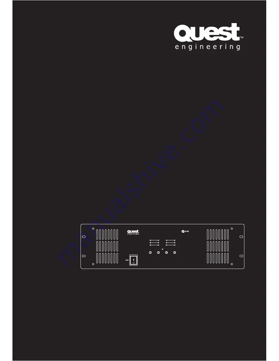
Q-Tech Commercial Series
QTA-
4060P/4120P
4 Channel Power Amplifiers
User Manual
ON
OFF
CH1
CH2
CH3
CH4
PROT
PEAK
SIGNAL
POWER
QTA 4060P
PUBLIC ADDRESS AMPLIFIER
Page 1: ...Q Tech Q Tech Commercial Series QTA 4060P 4120P 4 Channel Power Amplifiers User Manual ON OFF CH1 CH2 CH3 CH4 PROT PEAK SIGNAL POWER QTA 4060P PUBLIC ADDRESS AMPLIFIER...
Page 2: ...ents Safety Precautions 1 General Description 4 Features 4 Front Panel Layout 5 Rear Panel Layout 6 Connections 7 Applications 8 Block Diagram 9 Specifications 10 Dimensional Diagram 11 Technical Note...
Page 3: ...ty Symbol and Message Conventions Safety symbols described below are used in this manual to prevent bodily injury and property damage which could result from mishandling Before operating your product...
Page 4: ...metallic objects or flammable materials in the ventilation slots of the unit s cover as this may result in fire or electric shock When Installing the Unit Do not expose the unit to rain or an environm...
Page 5: ...direct sunlight near heaters or in locations generating sooty smoke or steam as doing otherwise may result in fire or electric shock When the Unit is in Use Do not place heavy objects on the unit as...
Page 6: ...es Rated outputs from 60W and 120W 24V DC interface 100V 70V line transformer isolated speaker outputs low impedance 4 ohms speaker outputs Four independent amps in a single chassis Four line level in...
Page 7: ...3 Volume 5 Channel volume control CH3 Volume 6 Channel volume control Signal CH1 CH2 CH3 CH4 7 Signal indicator LED When lit input signal is detected Peak CH1 CH2 CH3 CH4 8 Peaking indicator LED Prote...
Page 8: ...ie short the G and terminals together Inputs 3 6 Channel volume control For wiring unbalanced inputs tie short the G and terminals together Inputs 2 7 Channel volume control For wiring unbalanced inpu...
Page 9: ...70V 100V terminals cannot be used at the same time Impedances indicated in the figures represent the total speaker system load impedances WARNING Be sure to attach the supplied terminal cover after c...
Page 10: ...QTA 4060P 4120P User Manual User Manual Q Tech Commercial Series QTA 4060P 4120P 8 Applications QTA 4060P QTA 4120P Rear Panel Connections...
Page 11: ...QTA 4060P 4120P User Manual User Manual Q Tech Commercial Series QTA 4060P 4120P 9 Block Diagram...
Page 12: ...nce 200 1 Input Sensitivity 775mV 0dB Frequency Response 50Hz 16KHz distortion 1 5Db S N Ratio 15V microsecond T H D 1 Cool Method Copulsive Wind Cool Form Indicators Signal Protection Peaking Protect...
Page 13: ...al User Manual Q Tech Commercial Series QTA 4060P 4120P 11 Dimensional Diagram UNIT mm UNIT mm Keep all the unit s sides over 10cm away from objects that may obstruct air flow to prevent the unit s in...
Page 14: ...V and a terminal at one end for the negative return wire COM A low impedance terminal will be for 8 ohm speaker installations and is under no circumstances to be connected to a transformer type speake...
Page 15: ...he reason is that most ceiling speakers draw more than their claimed wattage The alternative would be to connect the speakers to the 4 watt transformer terminal giving you a theoretical total draw of...
Page 16: ...0 1W 100K 10W 1K 40W 250 0 5W 20K 15W 667 50W 200 1W 10K 20W 500 75W 133 2W 5K 25W 400 100W 100 3W 3 33K 30W 333 150W 66 7 5W 2K 35W 286 200W 50 100V plan P E x E Z 100x100 Z 10 000 Z P Power W Z Imp...
Page 17: ...QTA 4060P 4120P User Manual User Manual Q Tech Commercial Series QTA 4060P 4120P 15...
Page 18: ...QTA 4060P 4120P User Manual User Manual Q Tech Commercial Series QTA 4060P 4120P 16...
Page 19: ...QTA 4060P 4120P User Manual User Manual Q Tech Commercial Series QTA 4060P 4120P 17...
Page 20: ...www questaudio net Quest Engineering Pty Ltd 86 Derby St Pascoe Vale VIC 3055 Ph 613 9354 9133 Fax 613 9354 9233...