Smart LTE Module Series
Smart EVB G2 User Guide
Smart_EVB_G2_User_Guide 45 / 59
The schematic and pin assignment of J1302 are the same as J13
01’s.
SD Card Interface
4.10.
Smart EVB G2 provides an SD card interface J1101 for customers
to test the module’s SD card interface.
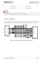
The following figure shows the simplified interface schematic for SD card interface on Smart EVB G2.
SD_CMD
120K
NM_51K
SD_DATA3
SD_DATA2
LDO5_1P8
SD_CLK
SD_DATA0
SD_DET
SD_DATA1
P1-DAT2
P2-CD/DAT3
P3-CMD
P4-VDD
P5-CLK
P8-DAT1
GND
P6-VSS
P7-DAT0
DETECTIVE
GND
GND
GND
1
2
3
4
5
6
7
8
9
10
11
12
13
SD_LDO11
33R
33R
33R
33R
33R
33R
1K
33pF
4.7uF
SD_LDO12
Module
R1
R2
R3
R4
R5
R6
NM_51K NM_10K NM_51K NM_51K
R7
R8
R9
R10
R11
R12
R13
D1
D2
D3
D4
D5
D6
D7
D8
C1
C2
SD Card Connector
Figure 37: Simplified Interface Schematic for SD Card Interface
7
RS232_CTS
I
Clear to send
8
RS232_RTS
O
Request to send
NOTE


