Smart LTE Module Series
Smart EVB G2 User Guide
Smart_EVB_G2_User_Guide 44 / 59
TXS0104 EPWR
RXD_3.3V
CTS_3.3V
TXD_3.3V
RXD_1.8V
CTS_1.8V
VCCA
Module
GND
GND
1.8V
VCCB
3.3V
DIN 1
ROUT 3
ROUT 2
ROUT 1
DIN 4
DIN 3
DIN 2
DIN 5
R1OUTB
FORCEON
/
3.3V
DOUT1
DOUT2
DOUT3
DOUT4
DOUT5
RIN3
RIN2
RIN1
VCC
GND
OE
SN65C 3238
RTS
TXD
CTS
RXD
GND
UART_TXD
UART_RTS
UART_RXD
UART_CTS
DB-9
/INVALID
FORCEOFF
TXD_1.8V
RTS_1.8V
RTS_3.3V
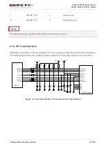
Figure 35: RS232 Level Match Circuit
The following figure shows the pin assignment of main UART port (J1301)
.
Figure 36: Pin Assignment of Main UART Port
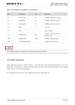
Table 10: Pin Definition of Main UART Port
J1401
Pin Name
I/O
Description
2
RS232_TXD
O
Transmit data
3
RS232_RXD
I
Receive data
5
RS232_GND
Ground
2
3
5
7
8


