Smart LTE Module Series
Smart EVB G2 User Guide
Smart_EVB_G2_User_Guide 30 / 59
LCM Interfaces
4.3.
4.3.1. Main LCM Interface
The Smart EVB G2 provides two LCM interfaces and can be equipped with two LCD modules for dual
display function. Currently the Smart EVB G2 provides two 5-inch 1280
×
720 HD resolution liquid crystal
displays for customers to test.
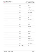
The following figure shows a reference circuit design for main LCM interface of the Smart EVB G2.
DSI0_CLK_P
LEDA
NC
LEDK
LPTE
NC (SDA-TP)
VIO18
NC (VTP-TP)
DSI0_LN3_P
LCD0_TE
LCD0_RST
DSI0_LN3_N
DSI0_LN2_P
DSI0_CLK_N
DSI0_LN2_N
RESET
LCD_ID
NC (SCL-TP)
NC (RST-TP)
NC (EINT-TP)
GND
VCC28
GND
MIPI_TDP3
MIPI_ TDN3
GND
MIPI_TDP2
MIPI_ TDN2
GND
MIPI_TDP1
MIPI_ TDN1
GND
LDO17_2V85
LDO 6_1V8
LCD_BL_A
LCD_BL_K1
1
2
3
4
5
6
7
8
9
10
12
13
14
15
16
17
18
19
20
21
22
23
24
25
26
27
MIPI_TDP0
MIPI_TDN0
GND
MIPI_TCP
MIPI_ TCN
29
28
30
3
4
5
6
3
4
5
6
3
4
5
6
3
4
5
6
DSI0_LN1_N
DSI0_LN1_P
DSI0_LN0_N
DSI0_LN0_P
1
2
3
4
5
6
11
1
2
1
2
1
2
1
2
100nF
4.7uF
1uF
Module
LCM
FL1
FL2
FL3
FL4
FL5
EMI filter
C3
C2
C1
NC
GND
GND
GND
GND
PMI_ MPP1
31
32
33
34
LCD_BL_K2
J0803
Figure 16: Reference Design for Main LCM Interface
The white LEDs (WLED) of main LCM interface are driven by the module. LCD_BL_A is the high voltage
source for powering a string of WLEDs. LCD_BL_K1 and LCD_BL_K2 are the two output drivers for
sinking the current from WLED strings.
NOTE


