


LTE Standard Module Series
EG915U_Series_Hardware_Design 46 / 81
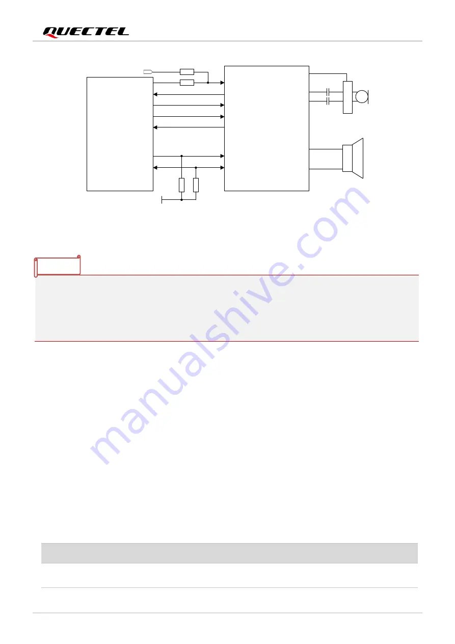
PCM_DIN
PCM_DOUT
PCM_SYNC
PCM_CLK
I2C_SCL
I2C_SDA
Module
4
.7
K
4
.7
K
BCLK
LRCK
DAC
ADC
SCL
SDA
B
IA
S
MICBIAS
INP
INN
LOUTP
LOUTN
Codec
1.8 V
External 26MHz Crystal
0R
NM 0R
CAM_MCLK
MCLK
Figure 22: Reference Circuit of I2 C and PCM Application with Audio Codec
1.
It is recommended to reserve an RC (R = 22 Ω, C = 22 pF) circuit on the PCM traces, especially for
PCM_CLK.
2. The I2 C interface supports simultaneous connection of multiple peripherals except for codec IC. In
other words, if a codec IC has been mounted on the I2 C bus, no other peripherals can be mounted; if
there is no codec IC on the bus, multiple peripherals can be mounted.
4.6. UART Interfaces
The module provides three UART interfaces: the main UART interface and the debug UART interface and
auxiliary UART. Their features are described as follows.
⚫
Main UART interface supports 4800 bps, 9600 bps, 19200 bps, 38400 bps, 57600 bps, 115200 bps,
230400 bps, 460800 bps and 921600 bps baud rates, and the default is 115200 bps. This interface is
used for data transmission and AT command communication.
⚫
Debug UART interface supports 921600 bps baud rate. It is used for the output of partial logs.
⚫
Auxiliary UART.
Table 14: Pin Definition of Main UART Interface
Pin Name
Pin No.
I/O
Description
Comment
MAIN_CTS
36
DO
DTE clear to send signal to
DCE (connect to DTE’s CTS)
1.8 V power domain.
If unused, keep it
NOTE


