


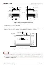
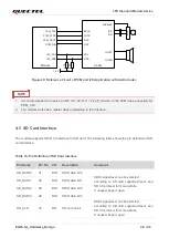
LTE Standard Module Series
EG25-GL_Hardware_Design 46 / 96
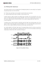
4.4 PCM and I2C Interfaces
The module provides one Pulse Code Modulation (PCM) digital interface for audio design, which supports
the following modes, and one I2C interface:
⚫
Primary mode (short frame synchronization, works as both master and slave)
⚫
Auxiliary mode (long frame synchronization, works as master only)
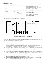
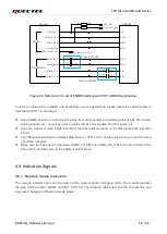
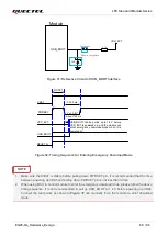
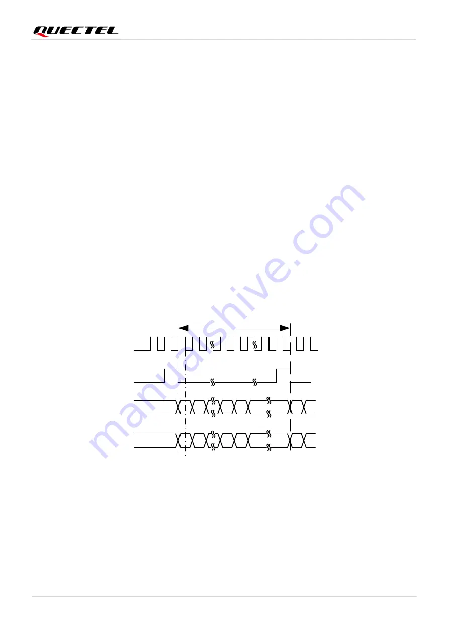
In primary mode, the data is sampled on the falling edge of the PCM_CLK and transmitted on the rising
edge. The PCM_SYNC falling edge represents the MSB. In this mode, the PCM interface supports 256,
512, 1024 or 2048 kHz PCM_CLK at 8 kHz PCM_SYNC, and also supports 4096 kHz PCM_CLK at
16 kHz PCM_SYNC.
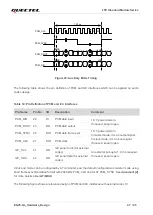
In auxiliary mode, the data is sampled on the falling edge of the PCM_CLK and transmitted on the rising
edge. The PCM_SYNC rising edge represents the MSB. In this mode, the PCM interface operates with a
256, 512, 1024 or 2048 kHz PCM_CLK and an 8 kHz, 50% duty cycle PCM_SYNC.
The module supports 16-bit linear data format. The following figures show the
primary mode’s timing
relationship with 8 kHz PCM_SYNC and 2048 kHz PCM_CLK, as well as the
auxiliary mode’s timing
relationship with 8 kHz PCM_SYNC and 256 kHz PCM_CLK.
PCM_CLK
PCM_SYNC
PCM_DOUT
MSB
LSB
MSB
1
2
256
255
PCM_DIN
MSB
LSB
MSB
125
μ
s
Figure 22: Primary Mode Timing