


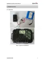


GL300W External Battery Kit User Manual
GL300WEBKUM001
-16-
3.4.
Indication LED
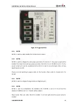
The Red LED is used to indicate the output of the power. It is controlled by the toggle switch
SW104 and the power output.
3.5.
Onboard Motion Sensor
If SW101 is set to ‘H’, the motion sensor will be disabled and the logical status of motion sensor
will always be ‘0’. If SW101 is set to ‘L’ then the motion sensor will be enabled. The logical status
of motion sensor will be ‘1’ when the PCU is in motion, and be ‘0’ when the PCU is in rest. Please
notice that there will be five minutes’ delay after the logical status of motion sensor change from
‘1’ to ‘0’.
The logical status of motion sensor will effect on the power output. Please refer to chapter 3.6
for detail.
3.6.
Relations between Logical Status and Power Output
Only when the logical status of digital input 1 and 2 are all 0, the power output can be disabled.
PCU will send the report on every logical status change to the backend server via GL300W. Please
refer to chapter 6.2 for detail.
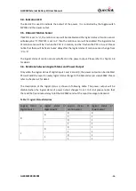
The description of the logical status is shown in following table. The power output will be
disabled when the logical status of power output changes from 1 to 0. But please notice that
there will be five minutes delay to let the GL300W send out the report message to backend.
Table 7: Logical Status Relations
Logical status of
digital input 1
Logical status of
digital input 2
Logical status of
motion sensor
Logical status of
Power output
0
0
0
0
1
1
1
0
1
1
1
1
0
0
1
1
1
1
0
1
1
1
Queclink
Confidential