background image

QS-CH2

2.3.

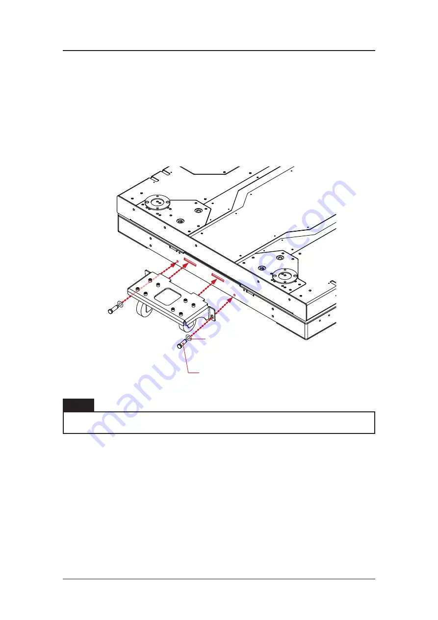
TRANSPORTATION WHEELS

Transportation wheels can be mounted for transportation purposes. Put the transporta-
tion wheels mounting bracket to the mounting points in the front and back of the QS-
CH2. Screw both bolts with nuts gradually one by one using 17 mm socket wrench until
the bracket is flush against the side of the device and platform is high enough to be
transported.

DIN 933 M10 x 35 bolt

DIN 9021 M10 washer

INFO

Transportation wheels can be mounted on CH-2 with attached payload.

User Manual R1.0

9

Summary of Contents for QS-CH2

Page 1: ......

Page 2: ......

Page 3: ...utions that reproduce key immersive elements such as surface textures acceleration engine vibrations and vehicle dynamics for multiple types of land air or sea vehicles Our motion system has been desi...

Page 4: ...from the simulation world QubicSystem com News CHECK OUR SOCIAL MEDIA Everything you wish to know is here facebook com qubicsystem SUPPORTED GAMES Racing games and professional simulation software Qub...

Page 5: ...2 3 Transportation wheels 9 2 4 Excursions 10 2 5 Dimensions 10 2 6 System specification 11 2 7 Power Requirements 12 3 Installation 13 3 1 Software Installation 13 3 2 Connecting with user PC 19 3 3...

Page 6: ...power switches off before plugging and unplugging the QS CH2 Dangerous voltages level can be present in power cabinet for a few minutes after turning off the machine Use the QS CH2 only for its intend...

Page 7: ...eit DO NOT use the QS CH2 if it has been damaged or any component is broken or missing Please contact technical support DO NOT use attachments or replacement parts not recommended or approved by the m...

Page 8: ...condi tion of the machine prior to use and adhering to safe operating procedures What must be done before turning on the machine Check if cables are mounted properly they are not stretched or loosely...

Page 9: ...and do not try to interrupt it DO NOT interrupt or change the weight of payload mounted to the QS CH2 during start up calibration To check if the platform is in the Motion Lock mode look at the main w...

Page 10: ...lcohol or drugs STOP USING the QS CH2 immediately if pain fatigue or any discomfort appears For every two hours of playing we recommend at least 15 MINUTES OF BREAK DO NOT put your hands or legs in th...

Page 11: ...on cockpit It is suited to work together with the Qubic System QS CH1 motion cockpit by providing additional over steering effect Platform is based on the Qubic System linear actuator technology which...

Page 12: ...QS CH2 2 2 PLATFORM LAYOUT AND ACTUATORS MOUNTING POINTS User Manual R1 0 7...

Page 13: ...4 x mounting points M8 x 1 25 Actuator foot mounting plate 4 x mounting points M8 x 1 25 Rear side actuator foot mounting points REAR Actuator foot mounting plate 4 x mounting points M8 x 1 25 Actuat...

Page 14: ...ing points in the front and back of the QS CH2 Screw both bolts with nuts gradually one by one using 17 mm socket wrench until the bracket is flush against the side of the device and platform is high...

Page 15: ...QS CH2 2 4 EXCURSIONS 2 5 DIMENSIONS User Manual R1 0 10...

Page 16: ...cture 2DOF Actuator stroke 100 mm Platform weight 160 kg Gross moving load 300 kg Excursions Yaw 7 2 7 2 Surge 50 mm 50 mm Maximum velocity 800 mm s Maximum acceleration 0 8G Value of acceleration is...

Page 17: ...ess test kW Average Power typical game kW 120 V power supply 1 1 5 12 4 0 7 0 06 230 V power supply 1 1 7 7 4 0 6 0 06 With heavy payload and or intensive simulation average power consumption may rise...

Page 18: ...MI Force SeatMI and MT Motion Theater licences To download the software visit QubicSystem com Download Once the QS CH2 is installed and connected correctly 1 Connect power supply cable to the wall soc...

Page 19: ...lower left corner will change to Connected 7 Check Action Center on the right side panel for a list of actions that requires at tention It is possible to solve them one by one or by pressing the Resol...

Page 20: ...agnostics Devices and select Configure 9 Choose correct layout from the list 0 T or 4 T 10 Scroll down in the window you can choose one of the operation modes INFO Q MODE is unavailable for 120V power...

Page 21: ...e game tile check profile details by clicking on it 12 Adjust the motion effects intensity to your preferences in the game profile window scroll down in the window to see all of the settings You can a...

Page 22: ...QS CH2 13 Activate profile by clicking the Activate button 14 Launch on the game by clicking the Run the game button User Manual R1 0 17...

Page 23: ...t not limited to the warranties of merchantability fitness for a par ticular purpose and non infringement In no event shall the authors or copyright holders be liable for any claim damages or other li...

Page 24: ...QS CH2 3 2 CONNECTING WITH USER PC INFO The base QS CH1 requires MC6 controller set in order to connect it to the user PC User Manual R1 0 19...

Page 25: ...QS CH2 3 3 CONNECTING WITH QS 220 PL EXTENED SET 4 ACTUATORS User Manual R1 0 20...

Page 26: ...NOT dispose of this product with stan dard household waste but dropped it off at a collection point for the disposal of Waste Electrical and Electronic Equipment for re cycling QS CH2 is an advanced...

Page 27: ...gligence an accident an impact for example Normal wear INFO If permitted under applicable law Motion Systems and its subsidiaries disclaim all liability for any damages unrelated to the material or ma...

Page 28: ...combining the QS CH2 with any unsuitable element including in par ticular power supplies chargers or any other elements not supplied or approved by Motion Systems for this product In the event of fail...

Page 29: ...itten permission of Motion Systems Specifications and information in this manual are subject to change at any time without obligation to notify any person of such revision or changes Illustrations are...

Page 30: ......

Page 31: ......

Reviews: