3
rd
Generation Dual Channel
Compact RDMS
TM
Telemetry Receiver-Combiner
15
Quasonix, Inc.
3.3.3
Electrical Signals
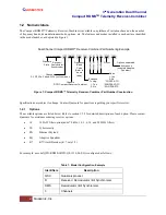
By default, the output data is valid on the falling edge of the clock, as shown in Figure 9. The polarity of the output
clock may be inverted by toggling the Clock Polarity setting in its web-based browser interface (RDMS™ Browser
Interface).
Figure 6: Baseband Signal Timing
The RF input to the receiver is a 50 ohm interface.
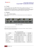
The CRC™ also provides a 70 MHz IF output for each channel for troubleshooting purposes. These IF outputs are
capped with 50 ohm terminators, and these should be left in place unless another 50 ohm load (such as a spectrum
analyzer) is connected instead.
Bit period
(360 deg)
User asserts data on rising edge
of TTL clock, rising edge of
ECL clock+ signal, or rizing
edge of TIA/EIA422 "A" clock
generator terminal
Clock jitter and data to clock
skew reference point
Tx samples DATA on
falling edge of TTL clock,
falling edge of EC)
signal, or falling edge of
TIA/EIA422 "A" clock
terminal.
data=1 (MARK)
data=0 (SPACE)
CLOCK
NRZL
DATA
Baseband Signal Timing - 0 degree clock
data=1 (MARK)


