background image

Chapter 11  In-service field maintenance for 5U enclosures

109

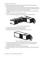
To replace a fan cooling module:

1. Retrieve the new FCM in its static-protected container, ready to access and use the new FCM immediately

upon removal of the faulty one.

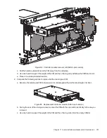
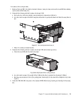
2. Complete the following actions to remove the faulty FCM:

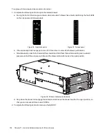
a. Facing the rear of the rack cabinet, press downward to release the FCM latch.

b. Use one hand to support the FCM's weight and the other to gently withdraw the FCM all the way from its

slot.

1

2Gb/s

1

2Gb/s

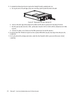
Figure 87 Fan cooling module removal

c. Place it in a static-protected location.

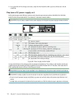
3. Complete the following actions to replace the faulty FCM with a tested, good one:

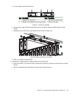
a. Orient the new FCM with the latch to the right.

Figure 88 Replacement fan cooling module

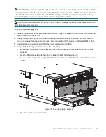
b. Use one hand to support the weight of the FCM and the other to guide it into the empty FCM slot.

c. Exerting even pressure to the center, gently press inward until it connects with the midplane and it locks

in place.

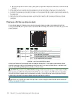
4. Verify the

FCM OK

LED is lit green on the replaced FCM after properly inserting and seating it in the empty

slot.

Summary of Contents for QXS Series

Page 1: ...QXS 5 Hardware Installation and Maintenance Guide 6 69090 01 Rev A...

Page 2: ...T STATEMENT 2023 Quantum Corporation All rights reserved Your right to copy this manual is limited by copyright law Making copies or adaptations without prior written authorization of Quantum Corporat...

Page 3: ...he 2U enclosure 20 Test enclosure electrical earth connection 21 Route 2U enclosure data cables and power cords 21 Route 2U enclosure host cables and expansion data cables 22 Route 2U enclosure power...

Page 4: ...ed management interface 62 Complete the preboard and onboard process 63 Storage volume replication 63 Co located replication configurations 64 Remote replication configurations 66 Set up storage volum...

Page 5: ...its carrier 101 Replace a 5U enclosure controller module 105 Replace a 5U fan cooling module 108 Replace a 5U power supply unit 110 A Technical specifications 113 B Standards and regulations 115 Inte...

Page 6: ...pansion modules 24 Figure 17 Sample invalid loop in red among 2U controller modules CMs and expansion modules 24 Figure 18 2U power cord routing to independent power distribution units 25 Figure 19 2U...

Page 7: ...ample of two remote sites each with a controller enclosure switch and its own host server 67 Figure 51 2U12 and 2U24 operator s panel fault LEDs 69 Figure 52 2U12 and 2U24 fault LEDs on carrier bezel...

Page 8: ...latch properly locked 104 Figure 82 Safety lock to release left drawer slide rail of lower drawer 105 Figure 83 Controller module LEDs to examine for fault conditions 106 Figure 84 Controller module r...

Page 9: ...n settings 59 Table 11 Factory default network port IP addresses 60 Table 12 Supported browsers 62 Table 13 2U enclosure non fault conditions 80 Table 14 5U enclosure non fault conditions 81 Table 15...

Page 10: ...tt Lake processor 16GB of cache and a custom RAID acceleration ASIC WARNING Heed all warnings and cautions on labeling and throughout this guide to reduce risk of personal injury or damage to equipmen...

Page 11: ...4 3 5 inch or 2 5 inch drive modules with adapters in carriers Two controller modules CMs Five fan cooling modules FCMs Two power supply units PSUs Four sideplane printed circuit boards PCBs two per d...

Page 12: ...ive coatings Each chassis is designed specifically for mounting in a rack cabinet 2U enclosure components The front panel area hosts an operator s panel and the drive modules l 2U12 Contains 3 5 inch...

Page 13: ...r lock drive module Prevents drive module removal when locked 5 Drive 3 Responds to commands for drive logically numbered 3 6 Operator s ops panel on left rack ear flange Connects to midplane provides...

Page 14: ...CM 5 Inverted PCM status LEDs Provides users with PCM status 6 Inverted PCM power switch Switches power on or off Figure 2 2U12 and 2U24 rear panel area 5U enclosure components The 5U84 chassis retain...

Page 15: ...awer 4 Drawer left side anti tamper lock Prevents drawer access when locked 5 Top drawer Drawer 1 Contains DDIC slots logically numbered from 0 to 41 6 Bottom drawer Drawer 2 Contains DDIC slots logic...

Page 16: ...d service 6 FCM pull handle 7 Power supply unit PSU Provides redundant regulation of power 8 PSU release latch Provides full contact with midplane or releases PSU for inspection and service 9 PSU pull...

Page 17: ...es to system controls Authorized service personnel only 8 Controller module CM Provides data redundancy and acts as the nerve center of the storage enclosure 9 Fan cooling module FCM Provides redundan...

Page 18: ...n 12Gb s data exchange with other expansion enclosures Figure 6 Controller module ports sample SAS 4 port Optional components Occasionally you may configure the storage enclosure to operate without al...

Page 19: ...otected area Do not further lighten the storage enclosure by removing other components Use this checklist performing each task only in the sequence presented after successful completion of the prior s...

Page 20: ...osure to a lift b For the 5U storage enclosures have three people use the provided belt straps to move the enclosure to a lift 2 Use a mechanical lift for positioning the storage enclosure and mountin...

Page 21: ...ve modules 4 Ensure the rack cabinet is suitable for use with the storage enclosure a A rack cabinet capable of holding 2U or 5U form factors that meets all UL and IEC safety requirements leveled in a...

Page 22: ...meeting all product specifications and providing a clean clear static protected environment prior to unpacking the enclosure 2 Complete the following actions to complete inspection of the 2U enclosure...

Page 23: ...but pertains to other rack types You must take all appropriate rack cabinet safety precautions before mounting a storage enclosure into a rack CAUTION Observe all the following directives l Always pl...

Page 24: ...er storage enclosures above heavier ones to maximize stability 7 Remove storage enclosures from the top of the rack cabinet to the bottom when emptying it Required equipment Qty Identification Outer r...

Page 25: ...bracket as far inward as possible then verify the entirety of the lower rail tab is visible just beyond the inner edge of the front rack mount bracket This step is crucial to safety and proper storage...

Page 26: ...that all mount bracket location pins fully seat in identical locations in the rack posts 10 Facing the rear of the rack cabinet insert a Phillips head M5 x 15 screw into the center hole of the rear mo...

Page 27: ...storage position l Follow local occupational health and safety guidelines and meet all requirements for manual material handling Mounting the storage enclosure into the rack cabinet is the most criti...

Page 28: ...rails removed rear components for clarity 3 Complete the following actions to properly secure the 2U chassis on the outer rails a Keep the 2U chassis stationary on the lift b Verify that both outer ra...

Page 29: ...rt a Panhead M5 x 8 screw into the operator s ops panel with an 8mm nut driver or a Philips screwdriver Figure 14 Installation of 2U operator s panel screw and cover c Hand tighten firmly against fron...

Page 30: ...ow all drive slots must hold either a DDIC or an optional blank carrier You may not leave any empty slots Test enclosure electrical earth connection After completion of all installation procedures the...

Page 31: ...ct data cables that best align with available controller module CM ports and your host environment Fault tolerance and performance are key factors in determining how to best optimize your particular s...

Page 32: ...ert a mini SAS data cable from SAS port C in the first expansion enclosure 1A and connect the other end to SAS port A in the second expansion enclosure 2A c Insert a mini SAS data cable from SAS port...

Page 33: ...B C A 1A 0A 0B 12Gb s 12Gb s Figure 16 Sample reverse cabling method among 2U controller modules CMs and expansion modules C A 3B C A 3A C A 2B C A 2A C A 1B C A 1A 0A 0B 12Gb s 12Gb s Figure 17 Sampl...

Page 34: ...ooling module PCM to power sources that comply with product specifications and labels l Always remove all power connections before you remove a PCM from the storage or expansion enclosure To route 2U...

Page 35: ...closures Figure 19 2U power cord surrounded by secure tie 6 Proceed with routing data cables in the next tasks leaving the power on sequence until after you complete all other cabling tasks and are fu...

Page 36: ...surge protection To unpack and prepare the 5U enclosure 1 Prepare the site for the storage enclosure installation This includes meeting all product specifications and providing a clean clear static pr...

Page 37: ...rack CAUTION Observe all the following directives l Always place the rack cabinet on a flat leveled surface Do not install a storage enclosure into a rack cabinet until you verify the rack cabinet is...

Page 38: ...both rail assemblies from their packaging 2 Orient the rail with the LH FRONT embossed on it to your left the other with the RH FRONT embossed on it to your right and each emboss toward you facing inw...

Page 39: ...center of the front rack mount bracket and barely tighten against the front rack post using an 8mm nut driver or a Philips screwdriver Figure 22 Insertion of 5U front mount bracket screw 6 Extend the...

Page 40: ...injury from tipping the rack follow all rack installation guidelines securing the rack cabinet to the floor with a concrete anchor kit l To avoid catastrophic failure of the rack assembly never excee...

Page 41: ...5U enclosure into the rack cabinet 1 Confirm that the outer rails are properly and securely installed in the rack cabinet 2 Confirm that the storage enclosure does not contain any drives so the chassi...

Page 42: ...k cabinet a Facing the front of the enclosure carefully exert even pressure on both sides of the storage enclosure front inserting the storage enclosure until the rack ear flanges are flush with the f...

Page 43: ...e Repeat the process for securing the right rack ear flange and replacing the right rack ear cover f Facing the rear of the enclosure insert and tighten an Panhead M5 x 8 screw through the chassis and...

Page 44: ...en the upper drawer a Facing the front of the storage enclosure press and hold both drawer pull handles while pulling outward b Stop as the drawer rails engage the safety lock latches and then access...

Page 45: ...k row in Drawer 1 then the back row in Drawer 2 The total number of populated drawer rows cannot differ by more than 1 row l Populate rows with DDICs that have the same form factor and same rotational...

Page 46: ...torage enclosure to a power source that has a safety electrical earth connection Have a qualified electrical engineer confirm the earth connection meets the product specifications CAUTION If you insta...

Page 47: ...t tolerant reverse cabling method since it provides a method of maintaining access to all enclosures in the chain even if one of the enclosures fails or requires removal If you use a straight through...

Page 48: ...and connect the other end to SAS port A in the second expansion enclosure 2A c Insert a mini SAS data cable from SAS port C in the second expansion enclosure 2A and connect the other end to SAS port A...

Page 49: ...s 12Gb s 0B 0A 1A A C A C A C A C A C A C 2A 3A 1B 2B 3B Figure 33 Sample invalid loop in red among 5U controller modules CMs and expansion modules Route 5U enclosure power cords This task provides di...

Page 50: ...ve the cable ties 2 Facing the rear of the rack cabinet connect a power cord connector to each PSU 3 Route the left power cord below the left outermost fan and connect the plug to an outlet on an inde...

Page 51: ...eason the storage enclosure automatically restarts after power restoration CAUTION Adhere to the following electrical safety guidelines l During installation never connect a power cord to a power supp...

Page 52: ...ready to power down the storage enclosure face the rear of the rack cabinet and switch off the power for the faulty PCM or PSU 2 Disconnect each power connector from the power distribution unit PDU 3...

Page 53: ...es of LEDs to reflect system status You can monitor the ops panel LEDs to determine system status in combination with the user interface content In the case of a system fault condition identified in t...

Page 54: ...ng Part of sequence as CM comes online on standby Off CM power is off CM is offline or CM has a fault condition Hardware fault Amber On CM hardware fault Off CM functioning properly Identify Blue On U...

Page 55: ...ff Not connected or link is down iSCSI 10GBase T link activity Green On Connected link is up Flashing Link activity Off Not connected or link is down Ethernet network port speed Amber On 1000base T ne...

Page 56: ...functioning properly Power on or standby Green On IOM power is on Amber On Part of standby sequence as EM comes online None Off IOM power is off ID Unit identification UID White On IOM UID active to l...

Page 57: ...carriers DDICs are in their correct slots that you install them in sets of 14 and that you properly engaged them by pressing firmly until each one locks into place on its midplane 3 Confirm you have...

Page 58: ...vides the first PSU with redundant power IMPORTANT The storage enclosure design requires two redundant power supply units PSUs You must plug each power cord into an independent power distribution unit...

Page 59: ...reinforce software messages about system health Use LEDs throughout the storage enclosure to determine if there is a critical fault The storage enclosure registers the following states using the ident...

Page 60: ...PD configuration error or 1 C bus fault Off Storage enclosure rear panel area modules functioning properly Logical status Amber On System component hardware fault drive cable or fanout card System com...

Page 61: ...mber On Drive hardware fault condition Flashing 3s on 1s off One or more arrays impacted by drive hardware fault conditions Off Drive module hardware functioning properly Drawer cable fault Amber On C...

Page 62: ...mal state no query for UID active OK to remove White On Ready for removal the cache is clear Off Do not remove the CM cache still contains unwritten data Cache status Green On Cache contains unwritten...

Page 63: ...ff Not connected or link is down iSCSI 10GBase T link activity Green On Connected link is up Flashing Link activity Off Not connected or link is down Ethernet network port speed Amber On 1000base T ne...

Page 64: ...functioning properly Power on or standby Green On IOM power is on Amber On Part of standby sequence as EM comes online None Off IOM power is off ID Unit identification UID White On IOM UID active to l...

Page 65: ...ive and scripted commands Disk Storage Management Utility DSMU Provides web based GUI JSON based Application Programming Interface API Provides means to conduct JSON based operations Redfish Swordfish...

Page 66: ...and installation of a device driver before the OS recognizes the USB device and can connect to a controller module To install a device driver 1 Navigate to https www seagate com support systems genera...

Page 67: ...ial vendor 0x210c product 0xa4a7 use_acm 1 You may also choose to incorporate the same information into the etc modules conf file To configure Linux for serial communication 1 Determine if the operati...

Page 68: ...y downloading and installing the Seagate device driver To configure Windows for serial communication 1 Start and configure the terminal emulator using the specified settings Parameter Value Parameter...

Page 69: ...roller 0B addresses IPv4 IP address 10 0 0 2 IP address 10 0 0 3 IP subnet mask 255 255 255 0 IP subnet mask 255 255 255 0 Gateway IP address 10 0 0 1 Gateway IP address 10 0 0 1 IPv6 Autoconfig Enabl...

Page 70: ...ctions to verify the new IP address a For IPv4 use the show network parameters command b For IPv6 use the show ipv6 network parameters command The result for each controller includes the IP address su...

Page 71: ...nd Expect browser warnings about security or privacy concerns related to self signed or untrusted certificates or invalid certificate authorities Bypass such warnings if you are confident of a secure...

Page 72: ...ng the key features that pertain to the storage enclosure to ensure your storage enclosure achieves optimal capacity and performance c Provision the storage enclosure by creating hosts and host groups...

Page 73: ...orts on controller enclosures to external network connections Cabling for replication requires planning and thought The samples included in this section are not exhaustive but should serve as an optim...

Page 74: ...h controller for I O traffic and the other pair connected to each controller for replication traffic Sample cabling for the first controller enclosure l Two SFP I O cables connect Controller 0A and tw...

Page 75: ...from replication traffic Both switches are dedicated to I O traffic Each one acts as the bridge to connect the site controller enclosures to the site host server The Ethernet WAN acts as the bridge t...

Page 76: ...RTANT Familiarize yourself with all replication related content in the Storage Management Guide before you begin To set up storage volume replication using the CLI 1 Find the port address on the secon...

Page 77: ...ler configurations wait a minimum of 10 minutes for each controller to complete synchronization with the other controller and to reach a ready state b For single controller configurations wait a minim...

Page 78: ...n but flashing indicates a non critical condition Some FRUs have more than one fault condition An asterisk indicates a fault condition 2U12 and 2U24 enclosure fault LEDs Visually inspect the front pan...

Page 79: ...control circuit has a hardware fault Fast flash 1s on 1s off Unit identification UID bit is set Slow flash 3s on 1s off Failed array Off Drive is functioning normally No AC power is present Figure 52...

Page 80: ...lude the following l Logs or events indicate a fault condition for the CM l The Hardware fault LED on the CM is steady or flashing amber l The Hardware fault LED for the SAS expansion port on the CM i...

Page 81: ...xpansion port Amber On Critical SAS cable fault Fast flash 1s on 1s off SAS unit identification UID active Slow flash 3s on 1s off Non critical SAS cable fault Off SAS expansion port functioning prope...

Page 82: ...witch is on PCM OK Off On Off On PCM fan speed is out of tolerance Off On Off PCM fan fault On Off On PCM hardware fault over temperature over voltage over current Off Flashing Off PCM is in standby m...

Page 83: ...Flashing Firmware update to PCM in progress Figure 56 Power cooling module fault LEDs 5U84 enclosure fault LEDs Visually inspect the front panel area for fault LEDs then locate the component fault LED...

Page 84: ...System software reports an informational condition for the array such as a rebuild operation with corresponding drives registering a fault condition Off System component hardware functioning properly...

Page 85: ...Off Cables functioning properly If all drives are functioning properly contact Technical Support for assistance Contact Technical Support for assistance Figure 58 5U84 drawer fault LEDs on drawer LED...

Page 86: ...n service documentation for details on how to minimize system disruption during service replacement of a controller module Fault conditions include the following l Logs or events indicate a fault cond...

Page 87: ...on 1s off Unit identification UID or locate is active for SAS expansion port Slow flash 3s on 1s off Non critical SAS cable fault Off SAS expansion port functioning properly Figure 61 SAS 12GB expans...

Page 88: ...tioning Fault conditions do require a system administrator to take an appropriate action to clear the fault condition The controller modules CMs allow you to choose from multiple fault isolation metho...

Page 89: ...n UID bit is set No action required Controller or expansion module LEDs no fault conditions LEDs other than CM amber fault LEDs SAS port amber fault LEDs System likely functioning properly Often no ac...

Page 90: ...nditions Drawer power and sideplane OK LED System functioning properly No action required Drawer data activity bar Drive module LEDs no fault conditions Amber flashing LED 1 second on 1 second off Dri...

Page 91: ...r of components interacting to create a viable data path each potentially creating an issue For example if a host side data error occurs it could be hardware such as the CM or a faulty cable or it cou...

Page 92: ...notifications related to hardware faults for replication data path components and follow recommended actions 3 Complete the following actions to address issues with replication volumes a In the Volum...

Page 93: ...is on replace the CM If it is flashing wait for the CM to come online 3 Determine the cause of a SAS port host side or CM side connection fault a Halt all input and output from the host to the storag...

Page 94: ...e system enclosure by removing power to both PCMs Do not power on until after you successfully replace them both l If one CM is failing remove power wait 1 minute then reset the CM 4 If the CM is stil...

Page 95: ...t hardware during installation or replacement to fully engage or secure it 2 Look for airflow restrictions at the front and rear of the storage enclosure Recommendation If a rack door blocks airflow b...

Page 96: ...the carriers in the drawer for these conditions l The carrier LED is off l The carrier fault amber LED is on not flashing 3 Select one of the following actions l If the carrier LED is off verify that...

Page 97: ...IOM still has a fault replace it within the specified 8 minutes with a new one 7 If installing a new CM or IOM that still has a fault remove it inspect connections for bent pins reinstall it then chec...

Page 98: ...es fully engage 3 Determine if one of the PCMs failed or is in the process of failing Verify all fans are running at a similar RPM If the impellers of a fan turn more than 2K RPM slower than the other...

Page 99: ...ve module or FRU prior to handling or replacing it l Do not remove a defective FRU until you have its functional replacement ready for insertion To adhere to safety precautions when replacing a FRU in...

Page 100: ...fault Fast flash 1s on 1s off Unit identification UID bit is set Slow flash 3s on 1s off Failed array Off Drive is functioning normally No AC power is present Figure 64 2U12 and 2U24 fault LEDs on car...

Page 101: ...lace a 2U enclosure drive module in its carrier 1 Complete the following actions to remove a faulty DDIC a Facing the front of the storage enclosure locate the DDIC with a fault condition b Using a th...

Page 102: ...solutions specific interaction that depends on your system configuration and software implementation including SAS zoning failover and failback procedures and multipath procedures An important featur...

Page 103: ...Off CMfunctioning properly OK to remove White On Ready for removal the cache is clear Off Do not remove the CM cache still contains unwritten data Figure 67 Controller module LEDs to examine for fault...

Page 104: ...e connected before 4 Verify that the Hardware normal LED is lit green on the replaced CM after properly inserting and seating it in the empty slot 5 Facing the front of the storage enclosure verify th...

Page 105: ...PCM fan speed is out of tolerance Off On Off PCM fan fault On Off On PCM hardware fault over temperature over voltage over current Off Flashing Off PCM is in standby mode Flashing Off Flashing Firmwar...

Page 106: ...significantly reduces airflow in the enclosure CAUTION Use only power cords supplied in the installation kit or those that meet product specifications CAUTION Adhere to power source and power connect...

Page 107: ...e latch of each PCM to the open position e Use one hand to support the weight of the PCM and the other to gently withdraw the PCM 12Gb s 12Gb s Figure 71 Power cooling module removal f Temporarily sto...

Page 108: ...Chapter 10 In service field maintenance for 2U enclosures 99 5 Facing the front of the storage enclosure verify that the Power On LED is green and there are no fault conditions...

Page 109: ...erve the caution label affixed to each drive module or FRU prior to handling or replacing it l Do not remove a defective FRU until you have its functional replacement ready for insertion To adhere to...

Page 110: ...3s on 1s off Drive in critical condition Failed array Off No AC power present Drive initialization in process Drive quarantined Figure 73 Drive fault LED on carrier bezel An important feature of the s...

Page 111: ...rawer panel b If the anti tamper lock is engaged use a T20 Torx driver to unlock both drawer pull handles c Simultaneously press both drawer latches inward and hold them there while exerting even outw...

Page 112: ...b press the DDIC release latch arrow to the right to release the DDIC from its seated position c Grasping the top of the carrier pull it upwards until it clears its drawer slot Figure 78 Removal of dr...

Page 113: ...lease latch open and unlocked Figure 81 Release latch properly locked e Verify that all drives are at the same level and all DDIC release latches are properly locked CAUTION Do not proceed to close th...

Page 114: ...ler modules CMs manage the flow of data to and from the storage enclosure Each CM provides a very specialized solutions specific interaction that depends on your system configuration and software impl...

Page 115: ...ctioning properly Hardware fault Amber On CM hardware fault Flashing Part of sequence as CM comes online on standby Off CM functioning properly OK to remove White On Ready for removal the cache is cle...

Page 116: ...m its slot e Place it in a static protected location 2 Complete the following actions to replace it with a tested good CM a Examine the tested good CM to make sure it is undamaged with pins that are s...

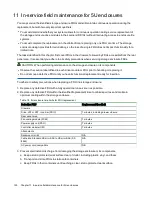
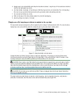
Page 117: ...hardware functioning properly Off FCM hardware fault FCM fault Amber On Fan speed is out of tolerance Communication with AP controller module CM lost Off FCM hardware functioning properly Figure 86 Fa...

Page 118: ...thdraw the FCM all the way from its slot 12Gb s 12Gb s Figure 87 Fan cooling module removal c Place it in a static protected location 3 Complete the following actions to replace the faulty FCM with a...

Page 119: ...mmunication with AP controller module CM lost On N A Off PSU hardware fault On Off PSU alert state or hardware fault over temperature over voltage or over current Off On Off AC power failed PSU not pr...

Page 120: ...n its static protected container ready to access and use the new PSU immediately upon removal of the faulty one 2 After you complete the proper shut down of the application and when you are ready to p...

Page 121: ...the weight of the PSU and the other to guide it into the empty PSU slot c Exerting even pressure to the center gently press inward until it connects with the midplane and it locks in place d Connect t...

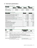
Page 122: ...ller module CM up to 0 70Kg up to 1 50 lb 2U enclosure power cooling module PCM 1 45Kg 3 20 lb 5U enclosure fan cooling module FCM 0 80Kg 1 80 lb 5U enclosure power supply unit PSU 0 70Kg 1 50 lb 2U r...

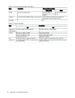
Page 123: ...Table 21 Environmental specifications continued Type Description 2U 5U Input power requirements 100VAC to 240VAC 50Hz to 60Hz 200VAC to 240VAC 50Hz to 60Hz Voltage Max output 764W or 580W Max output 2...

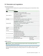
Page 124: ...Zealand VCCI Class A Japan KN 32 Class A KN 35 S Korea CNS 13438 Class A Taiwan Harmonics EN 61000 3 2 EU Flicker EN 61000 3 3 EU Immunity EN 55024 EU KN 24 KN 35 S Korea Environmental standards The...

Page 125: ...116 Appendix B Standards and regulations Contact your supplier for a copy of the Recycling Procedures applicable to your country...

Page 126: ...enclosure cabling 21 37 dimensions 113 installation checklist 10 site requirements 11 troubleshooting basic steps 81 weight 113 F failure hardware 81 86 cable connector or switch 82 87 88 drive module...

Page 127: ...packaging 13 27 storage enclosure 13 27 S safety precautions electrical 22 37 equipment disposal 115 installation 18 31 rack cabinet 14 28 SAS cabling 22 38 sensors temperature 68 shipment original p...

Page 128: ...contact the Quantum Customer Support Center Region Support Contact North America 1 800 284 5101 toll free 1 720 249 5700 EMEA 800 7826 8888 toll free 49 6131 324 185 Asia Pacific 800 7826 8887 toll fr...

Page 129: ...estrate protect and enrich data across its lifecycle providing enhanced intelligence and actionable insights Leading organizations in cloud services entertainment government research education transpo...

Reviews: