Quantum Optional X520 Dual Port 10 GbE Card Installation Instructions Manual Download Page 1

6-67765-01 Rev C, March 2014

*6-67765-01 C*

© 2014 Quantum Corporation. All rights reserved. Quantum, the Quantum logo, DLT, DLTtape, the DLTtape logo, SuperLoader, 
Scalar, DXi, StorageCare, StorNext, GoProtect, and Vision are registered trademarks of Quantum Corporation and its affiliates 
in the United States and/or other countries. All other trademarks are the property of their respective owners. Quantum 
specifications are subject to change.

Quantum DXi-Series: 

Optional Network Card 

Installation Instructions

The following network card options are available for supported DXi-Series 

configurations:

Dual port 10 GbE (X520) card

 - Provides two 10 GbE (SFP+) Ethernet ports 

for supported DXi4xxx configurations (DXi4700 or higher), or for supported 

DXi6xxx configurations (DXi6800 or higher) (see 

Figure 1

).

Quad port 1 GbE (i350) card

 - Provides four 1 GbE Ethernet ports for 

supported DXi6xxx configurations (DXi6800 or higher) (see 

Figure 2

).

Note:

If you are installing the optional network card as part of a new DXi 

installation, do not use this instructions document. Instead, follow the 

instructions in the 

Installation Guide

 that came with your new DXi.

Note:

This document is not for use with DXi4500, DXi4600, DXi6500, or 

DXi6700 systems.

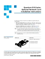
Figure 1  Optional X520 Dual 
Port 10 GbE Card

Illustration

Description

Dual port 10 GbE card (X520)

PN 9-02898-01 (Optical)
PN 9-02898-02 (Twinax)

Summary of Contents for Optional X520 Dual Port 10 GbE Card

Page 1: ... configurations Dual port 10 GbE X520 card Provides two 10 GbE SFP Ethernet ports for supported DXi4xxx configurations DXi4700 or higher or for supported DXi6xxx configurations DXi6800 or higher see Figure 1 Quad port 1 GbE i350 card Provides four 1 GbE Ethernet ports for supported DXi6xxx configurations DXi6800 or higher see Figure 2 Note If you are installing the optional network card as part of...

Page 2: ...the System on page 12 Preparing for the Upgrade WARNING To prevent the risk of electrical shock bodily injury or damage to the equipment read all instructions and warnings in the Quantum Products System Safety and Regulatory Information Guide that shipped with your system The guide is also available at http quantum com cssp Before you install the optional network card make the following preparatio...

Page 3: ...shipping bag or on an antistatic mat Wear anti static wrist bands when unpacking and handling the units and avoid touching connectors and other components Note Dry climates and cold weather heating environments have lower relative humidity and are more likely to produce static electricity Shutting Down the System To shut down the system Caution Before shutting down the DXi make sure that all backu...

Page 4: ...electric shock Caution Use appropriate ESD precautions including the use of a grounding strap when working inside the Node 1 If installed remove the front bezel by lifting the latch on the left side of the bezel 2 Disconnect all power SAS Ethernet and Fibre Channel cables from the rear of the Node Make sure to label the cables so they can be easily identified when they are re connected to the Node...

Page 5: ... J slots 6 Lift the Node up and away from the rack and place it on a flat stable surface WARNING The DXi Node including hard drives weighs more than 50 pounds 22 7 kg A minimum of two people are required to lift the chassis 7 Press and hold the power button on the front of the Node for three seconds to fully drain the system of stored power prior to removing the cover see Figure 5 Inner slide rail...

Page 6: ...tch release lock counterclockwise to the unlocked position see Figure 6 Figure 6 Removing the Node Cover 9 Lift the latch on top of the Node and slide the cover back 10 Grasp the cover on both sides and carefully lift the cover away from the Node Figure 7 illustrates the interior of the DXi Node with the cover removed Power Button System Node Front Node cover Latch Latch release lock ...

Page 7: ...d in three expansion card risers Install the optional network card in the correct slot in expansion card riser 1 see Figure 8 Supported DXi4xxx Models DXi4700 and higher Install the optional network card in slot 1 Supported DXi6xxx Models DXi6800 and higher Install the optional network card in slot 2 Note Depending on the model your DXi may include additional expansion cards compared to what is sh...

Page 8: ...n the system board see Figure 9 Figure 9 Removing and Installing the Expansion Card Riser 1 2 Press the tab to release the expansion card latch and rotate the latch away from the expansion card riser see Figure 10 Note Depending on the DXi model one or more expansion cards may already be installed in expansion card riser 1 Do not remove any installed cards from expansion card riser 1 Supported DXi...

Page 9: ...he expansion card connector 5 Insert the card edge connector firmly into the expansion card connector until the card is fully seated Make sure the card is inserted into the correct slot Supported DXi4xxx Models DXi4700 and higher Install the optional network card in slot 1 Supported DXi6xxx Models DXi6800 and higher Install the optional network card in slot 2 6 Close the expansion card latch 7 Hol...

Page 10: ... Replacing the Node Cover 2 Place the cover onto the Node chassis and offset the cover slightly back so that it clears the chassis hooks and lays flush on the chassis 3 Push down the latch to move the cover into the closed position 4 Rotate the latch release lock in a clockwise direction to secure the cover 5 Pull the inner slide rails out of the rack until they lock into place see Figure 12 Node ...

Page 11: ...uarely aligned with the rack as you slide it in 9 If applicable replace the front bezel by inserting the right side of the bezel into the slots on the Node and then snapping the left side of the bezel into place 10 Reconnect all power SAS Ethernet and Fibre Channel cables on the rear of the Node Note For detailed system cabling information see the Installation Guide for your DXi system 11 Connect ...

Page 12: ...y on the rear of the module displays 99 approximately 120 seconds 2 Press the power button on the front of the Node see Figure 13 Wait for the system to boot This can take up to 30 minutes Figure 13 Node Power Button 3 Navigate to the Configuration System Network page in the remote management console and verify that the new network ports are available to the DXi The new ports should display under ...

Reviews: