background image

9530/8530 Manual Version 4.5 

Page 47 


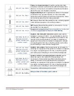
IEC 417, No. 5020 

Frame or chassis terminal

. Used for points other than 

protective conductor and functional earth terminals where 
there is a connection to accessible conductive terminals to 
advise the user of a chassis connection.  


IEC 417, No. 5021 

Equipotentiality 

Used in applications where it is important 

to indicate to the operator that two or more accessible 
functional earth terminals or points are equipotential.  More 
for functional rather than for safety purposes  


IEC 417, No. 5007 

On

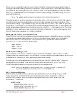
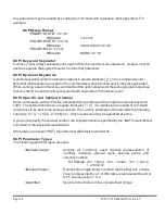
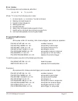
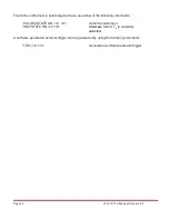
 (Supply) Note that this symbol is a bar, normally applied 

in the vertical orientation. It is not the number 1.  


IEC 417, No. 5008 

Off

 (Supply) Note that this symbol is a true circle. It is not 

the number 0 or the letter O.  


IEC 417, No. 5172 

Equipment protected by 

double insulation or reinforced 

insulation

 (equivalent to Class II if IEC 60536) 


ISO 3864, No. B.3.6 

Background color - 
yellow; symbol and 

outline - black 

Caution, risk of electric shock

 Generally used only for 

voltages in excess of 1000 V.  It is permissible to use it to 
indicate lower voltages if an explanation is provided in the 
manual. Color requirements do not apply to markings on 
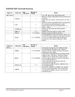
equipment if the symbol is molded or engraved to a depth 
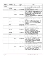
or raised height of 0.5 mm, or that the symbol and outline 
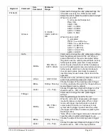
are contrasting in color with the background.  


IEC 417, No. 5041 

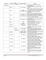
Background color - 
yellow; symbol and 

outline - black 

Caution, hot surface

 Color requirements do not apply to 

markings on equipment if the symbol is molded or engraved 
to a depth or raised height of 0.5 mm, or that the symbol 
and outline are contrasting in color with the background.  


ISO 3864, No. B.3.1 

Background color - 
yellow; symbol and 

outline - black 

Caution (refer to accompanying documents)

 used to 

direct the user to the instruction manual where it is 
necessary to follow certain specified instructions where 
safety is involved. Color requirements do not apply to 
markings on equipment if the symbol is molded or engraved 
to a depth or raised height of 0.5 mm, or that the symbol 
and outline are contrasting in color with the background.  


IEC 417, No. 5268-a 

In-position of bistable push control


IEC 417, No. 5269-a 

Out-position of bistable push control


Summary of Contents for 8530 Series

Page 1: ...Rev 4 5 9530 8530 Series Pulse Generator Operating Manual QUANTUM COMPOSERS INC PO Box 4248 Bozeman MT 59772 406 582 0227 phone 406 582 0237 fax www quantumcomposers com ...

Page 2: ...530 FRONT PANEL 10 SelectingMenus 10 SelectingMenu Items 11 NumericInput Mode 11 EnteringNon Numeric Parameters 11 EnablingSystem Output 11 Enable DisableChannel Output 11 Rearmingthe Channel Timers 11 SettingPulse Timing Parameters 11 SettingPulse Output Parameters 12 UsingtheOutput Multiplexer 12 SettingSystem Internal Rate Parameters 12 5 9530 MENUS 13 9530 MAI N MENU STRUCTURE 13 System Mode M...

Page 3: ...e Output Configuration 22 SettingChannel of Operation 23 Delayingthe Start of Channel Output 23 Setting the Sync Source 23 CHANNEL ADVANCED MENU 23 Configuringthe Channel Multiplexer 24 Setting Channel Gate Control 24 TRIGGER MENU 24 Enabling System Trigger 24 GATE MENU 25 Enabling System Gates 25 6 OPERATING THE 9530 8530 26 QUICK START NORMAL INTERNAL RATE GENERATOR OPERATION 26 QUICK START NORM...

Page 4: ...8530 SCPI COMMAND SUMMARY 37 IEEE 488 2 COMMON COMMANDS 42 8 APPENDIX A SPECIFICATIONS 43 9530 8530 Specifications 43 9 APPENDIX B SAFETY SYMBOLS 46 Safety Marking Symbols 46 10 APPENDIX C COM 48 Ethernet Interface Overview 48 11 APPENDIX D ETHERNET CONNECTIVITY 49 DETERMINING IP ADDRESS 49 TESTING ETHERNET COMMUNICATION 51 12 APPENDIX E DUAL TRIGGER INPUT 54 DT15 DUAL TRIGGER MODULE 54 9530 SCPI ...

Page 5: ...t Function 58 Using the Burst Increment Function 59 15 APPENDIX H EXTERNAL CLOCK 60 9530 8530 External Clock Operation 60 Usingtheexternalclockfunction 60 16 APPENDIX I 8530 BOARD LEVEL OPTION 61 8530 Board Level Connection Information 61 8530 BOARD LEVEL OVERVIEW 61 DIGITAL CONTROL BOARD CONNECTION INFORMATION 61 DIGITAL OUTPUT BOARD CONNECTION INFORMATION 64 MOUNTING INFORMATION 64 ...

Page 6: ... one of the following methods Phone 406 582 0227 Fax 406 582 0237 Internet www quantumcomposers com Warranty In addition to a 30 day money back guarantee the 9530 has a two year limited warranty from the date of delivery This warranty covers defects in materials and workmanship Quantum Composers will repair or replace any defective unit Contact us for information on obtaining warranty service Pack...

Page 7: ...ns If possible familiarize yourself with the equipment being tested and the location of its high voltage points However remember that high voltage may appear at unexpected points in defective equipment Do not expose high voltage needlessly Remove housing and covers only when necessary Turn off equipment while making test connections in high voltage circuits Discharge high voltage capacitors after ...

Page 8: ... right side of the display contains the title of the currently displayed menu The rest of the display is used for system parameters The display brightness may be adjusted allowing the instrument to be used under various lighting conditions Description of Front Panel Area Keypads Two keypad areas provide fast access to various menus and easy editing of system parameters Menu Keypad Provides one tou...

Page 9: ...pulses can be generated the timer must be armed and then receive a start pulse Arming the counter is done by pressing the Run Stop key With external trigger disabled the Run Stop key also generates the start command for the counter With external trigger enabled the external trigger provides the start pulse In either case once started the counter operation is determined by the System Mode Generator...

Page 10: ...f multiplexers This allows routing of any or all Channel Timers to any or all of the units outputs In the normal mode of operation the output of the nth Channel Timer is routed to the nth output connector As an example if a double pulse is required on Channel A one can multiplex the Channel A timer with the Channel B timer then adjust each timer to provide the necessary pulses Dependent Independen...

Page 11: ...nd the Down arrow disables the item Enabling System Output The Run Stop key is used to arm the system With external trigger disabled the key will arm and start pulse output With external trigger enabled the key will arm the pulse generator Pulse outputs then starts after the first valid trigger input Pressing the Run Stop key a second time disables the pulse generator Enable Disable Channel Output...

Page 12: ...nnel includes a multiplexer which allows routing ofany or all of the timer outputs to the physical output This allows double pulses and other complex pulse trains to be generated HGFEDCBA MUX 00000101 The multiplexer is represented by an n bit binary number as shown above N is the number of channels Each bit represents a channel timer which is enabled by setting the bit to one In the above example...

Page 13: ...system is first powered up or if a recall 0 command is entered System Mode Menu Mode Continuous Mode Single Shot Rearm the channels Mode Continuous T0 Period Mode Duty Cycle T0 Period Mode Duty Cycle On Set the n pulses Off Set the m pulses Mode Burst n pulses to produce Mode Burst T0 Period Rearm the channels Rearm the channels Rearm the channels Press the Page Button Change System Modes Clock Ra...

Page 14: ...ings Name The name associated with the current location The action needed to Store the information Recall Menu Recall Choose the location to restore the settings from Name The name associated with the current location The action needed to Recall the information Auxiliary Menu Screen to let the user know that there maybe updates on the Quantum Composers website for their unit Screen to let the user...

Page 15: ...desired delay from the sync source Enable Disable Channel Wid Set the desired pulse width Dly Set the desired delay from the sync source Press the Page Button Change Channel Mode Enable Disable Channel Pol Active High Low Output Out TTL CMOS Enable Disable Channel Mode Normal Enable Disable Channel Sync Source T0 Wait 0 Pulses Enable Disable Channel Mode Single Shot Enable Disable Channel Sync Sou...

Page 16: ...h Low Ch HGFE DCBA Mux 0000 0001 Enable Disable Channel Ch Gate Output Inh Logic Active High Low Trigger Menu By pressing the Trigger button the trigger menu will be entered Trigger Menu Mode Disabled Change Trigger Mode Mode Triggered Level 2 50 Volts Edge Rising Falling Edge Gate Menu By pressing the Gate button the gate menu will be entered Gate Menu Mode Disabled Change Gate Mode Mode Pulse In...

Page 17: ...pulse Duty Cycle On Off N number of pulses to generated for each T0 pulse M number of pulses to inhibit for each T0 pulse NOTE Any mode may be started by either the RUN STOP key in the internal trigger mode or armed by the RUN STOP key and started by an external trigger in the external trigger mode In the single shot and burst modes internally triggered the unit disarms itself at the end of the pu...

Page 18: ...ut Reference Ref Out Selects the source and frequency of the output reference for synchronizing with the external system components System Configuration Menu Interface RS 232 Baud Rate 115200 Echo Disabled Auto Enabled Mark LCD 4 Key Rate 50 ms Key Volume 10 Press the Page Button Change System SerialInterface Modes Interface Ethernet Auto Enabled Mark LCD 4 Key Rate 50 ms Key Volume 10 Interface U...

Page 19: ... repeat when held down Key Vol Sets the beep volume for the keypad Setting the Auto Start Mode The auto start feature can be set be entering the system configuration menu and pressing the Page button twice The unit may be configured to automatically start generating pulses after power up Setting the Display Decimal Mark The display mark feature can be changed be entering the system configuration m...

Page 20: ...hoose the location to restore the settings from Name The name associated with the current location The action needed to Recall the information Recalling System Configurations The recall menu can be accessed by pressing the menu button until that screen is entered Use the following procedure to recall a stored or default system configuration Enter the Recall Menu Select a configuration number From ...

Page 21: ...ontacting customer service for troubleshooting help Setting Channel Mode of Operation Channel Menu Enable Disable Channel Wid Set the desired pulse width Dly Set the desired delay from the sync source Press the Page Button Change Channel Output Mode Enable Disable Channel Pol Active High Low Output Out TTL CMOS Enable Disable Channel Mode Normal Enable Disable Channel Sync Source T0 Wait 0 Pulses ...

Page 22: ...ble Disable Channel Wid Set the desired pulse width Dly Set the desired delay from the sync source Enabling Channel Output The channel menu can be found by pressing the desired channel button At the top of each of the channel menu page is a parameter to enable or disable the channel Each channel may be individually controlled Setting the Channel Timing Parameters To define a pulse requires two par...

Page 23: ...e Channel menu Wait Sets the number of T0 pulses to wait until enabling the channel output Setting the Sync Source To change the sync source enter the channel menu and press the page button until the source screen is entered Although each channel receives its start pulse from the internal T0 pulse logically the start pulse can be assigned such that the delay entered is relative to the T0 pulse or ...

Page 24: ...r active high or active low Pulse Inhibit method the gate prevents the channel from being triggered by the channel s trigger source pulse If a pulse has already started when the gate disables the channel the pulse will continue normal output but will not restart on the next trigger pulse Output Inhibit method the gate leaves the base triggering alone and enables disables the output directly If a p...

Page 25: ...l 2 50 Volts Enabling System Gates The gate menu can be entered by pressing the Gate button To enable the use of the gate input trigger inhibit or output control for all channels simultaneously or on a per channel basis set the following parameters in the gate menu Mode Selects between disabling the Gate inputs and method of output control Level Sets the gating threshold Logic Sets the active logi...

Page 26: ... Stop key a second time to stop generating pulses Quick Start Normal External Trigger Operation To generate a single pulse for every external trigger event based on the default configuration 0 the following parameters need to be set System Mode Enter the System Mode menu by pressing the Menu button until the System Mode menu is selected Select Single Shot mode Trigger Menu Enter the Trigger Menu b...

Page 27: ...e Run Stop button generates a stream of N T0 pulses where the N is specified by the Burst parameter The rate is specified in the Rate menu Pressing the Run Stop button while in the burst is in process will stop the output After the burst has been completed pressing the Run Stop button will generate another burst To generate a burst of pulses set Within the System Mode menu o Select mode to be Burs...

Page 28: ...ngle Shot Function The Single Shot mode generates a single pulse every time the Run Stop key is pressed To use the channels single shot mode set Within the Channel menu o Enable the channel output o Set the delay desired o Set the pulse width desired o Set the mode to Single Shot Using the Channel Burst Mode The burst mode generates a burst of pulses every time the Run Stop key is pressed To use t...

Page 29: ...desired mode Pressing the Run Stop button will arm the unit Once the unit is armed it will start generating pulses once the external gate is in the active state Pressing the Run Stop key again will disarm the unit Using the Channel Gating Function Each channel may use the external input to gate or control its output The gate controls the triggering of the channel To use the channel gate set the fo...

Page 30: ...0 of the incoming signal o Select either rising or falling edge for the unit to trigger on Pressing the Run Stop button will arm the unit Once the unit is armed it will generate a set of pulses for every external trigger received The units timer is reset at the end of a burst and will generate another set of pulses upon receiving a new trigger Triggers that occur in the middle of a burst will be i...

Page 31: ...than 10 ms may cause the unit to not respond properly It is advised to wait until a response from the previous command is received before sending the next command WARNING When communicating with the unit USB Serial or Ethernet avoid sending any commands that include the character as the unit is booting up This may result in an undesired lockup of the instrument RS 232 Interface Overview The serial...

Page 32: ...rator can be set using the SCPI command SYSTem COMMunicate SERial USB n where n can be 4800 9600 19200 38400 57600 or 115200 USB 2 0 specification is used The USB cable can be removed without ejecting the device in the operating system environment Ethernet Interface Overview An Ethernet interface is alsostandard on the 9530 Refer toAppendix C included at the end of this manual for more information...

Page 33: ...IEEE 488 2 Common Commands control and manage generic system functions such as reset configuration storage and identification Common commands always begin with the asterisk character and may include parameters The parameters are separated from the command pneumonic by a space character For Example RST cr lf RCL 1 cr lf IDN cr lf SCPI Command Keywords The commands are shown as a mixture of upper an...

Page 34: ...ied Channel Some commands such as PULSe allow specifying a channel with an optional numeric keyword suffix The suffix will be shown in square brackets 1 2 The brackets are not part of command and are not to be sent to the pulse generator The numeric parameters correspond to the following channels 0 T0 1 ChA 2 ChB etc Only one channel may be specified at a time If you do not specify the channel num...

Page 35: ...sets pulse width to 20 ms PULSE1 DELAY 0 0023 cr lf sets delay to 2 3 ms PULSE0 MODE NORM cr lf sets system mode to continuous PULSE0 PER 0 1 cr lf sets period to 100 ms 10 Hz PULSE0 TRIG MODE DIS cr lf disables the external trigger To start the pulses use either of the following commands PULSE0 STATE ON cr lf starts the pulses INST STATE ON cr lf alternate form to start pulses Example 2 25μs puls...

Page 36: ...ode use either of the following commands PULSE0 STATE ON cr lf Arms the instrument INST STATE ON cr lf Alternate form if T0 is currently selected A software generated external trigger can be generated by using the following command TRG cr lf Generates a software external trigger ...

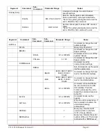
Page 37: ...ommand is applied to T0 If T0 is selected all outputs are affected Enabling T0 is the same as pressing the RUN button Keyword Command Sub Command Parameter Range Notes DISPlay Command to change the units display settings ENABle 0 1 or OFF ON Enables Disables the display also locks the keypad Once the system is rebooted the display will default to the on state MODe 0 1 or OFF ON Command to enable d...

Page 38: ...99 999 Changes the number of pulses to output when the system is in burst mode Note The commas should be omitted PCOunter 1 9 999 999 Changes the number of on pulses to output when the system is in Duty Cycle mode Note The commas should be omitted OCOunter 1 9 999 999 Changes the number of off pulses to suppress when the system is in Duty Cycle mode Note The commas should be omitted ICLock Submenu...

Page 39: ...hannel can be setup individually be aware of insertion delay for each mode this is listed in the appendix LOGic LOW HIGH Choose active Low will allow pulses when low or active High will allow pulses when high EDGe RISing FALLing Choose the edge of the incoming pulse to trigger on Only used when the option for the gate to be a second trigger input is enabled LEVel 20 15 V Choose the gate level thre...

Page 40: ...o change the channels output parameters MODe TTL ADJustable Allows the user to select either TTL logic mode or Adjustable voltage output mode AMPLitude 2 0 to 20 V Allows the user to select the voltage potential for Adjustable output mode CMODe NORMal SINGle BURSt DCYCle Allows the user to select the pattern of outputs to use on the channel level BCOunter 1 to 9 999 999 When the channel is in Burs...

Page 41: ... or off the systems beeper VOLume 0 100 Command to change the units beeper volume COMMunicate Command to set the communication settings SERial Sub Command to set the serial interface parameters BAUD 4800 9600 19200 38400 57600 115200 Command to change the baud rate for the RS 232 interface USB 4800 9600 19200 38400 57600 115200 Command to change the baud rate for the USB interface ECHo 0 1 or OFF ...

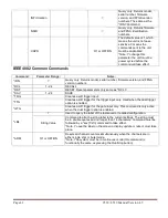
Page 42: ... as RCL 0 SAV 1 24 SAVE TRG Creates a soft trigger input TTG Creates a soft trigger for the trigger input only Used when the dual trigger option is enabled GTG Creates a soft trigger for the gate input only This command is only active when the dual trigger option is enabled LBL Used to query the label of the last saved or recalled configuration String Value Command to attach a string label to the ...

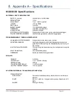
Page 43: ...CHANNEL OUTPUT MODES Single shot burst duty cycle normal CONTROL MODES Internally triggered externally triggered and external gate Each channel may be independently set to any of the modes OUTPUT MULTIPLEXER Timing of any all channels may be multiplexed to any all outputs WAIT FUNCTION 0 to 9 999 999 pulses TIMEBASE Same as internal rate generator DELAYS RANGE 0 1000 s ACCURACY 1 ns 0 0001 x Delay...

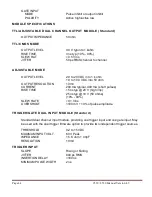
Page 44: ... into 50 ohm OUTPUT RESOLUTION 10 mV CURRENT 200 mA typical 400 mA short pulses RISE TIME 15 ns typ 20 V high imp 25 ns typ 10 V 50 ohms 10 90 SLEW RATE 0 1 V ns OVERSHOOT 100 mV 10 of pulse amplitude TRIGGER GATE DUAL INPUT MODULE Standard Standard dual channel input module providing one trigger input and one gate input May be used with the dual trigger firmware option to provide two independent ...

Page 45: ...IBIT DELAY 120 ns OUTPUT INHIBIT DELAY 50 ns STANDARD FEATURES COMMUNICATIONS USB RS232 EXTERNAL CLOCK IN 10 to 100 MHz in 1 MHz increments EXTERNAL CLOCK OUT T0 Rate Chan 2x ExtPLL 1 ExtPLL ExtPLL Ext 40 MHz 20 MHz 10 MHz 5 MHz and Disabled GENERAL STORAGE 24 storage bins DIMENSIONS 19 x 10 x 1 75 WEIGHT 8 lbs POWER 100 240 VAC 50 60 Hz 3 A FUSE Qty 2 630 mA 250 V Time lag ...

Page 46: ...ous operation This section provides a description of the safety marking symbols that appear on the instrument These symbols provide information about potentially dangerous situations which can result in death injury or damage to the instrument and other components Symbol Publication Description Comment IEC 417 No 5031 Direct current Vdc may be used on rating labels IEC 417 No 5032 Alternating curr...

Page 47: ...s in excess of 1000 V It is permissible to use it to indicate lower voltages if an explanation is provided in the manual Color requirements do not apply to markings on equipment if the symbol is molded or engraved to a depth or raised height of 0 5 mm or that the symbol and outline are contrasting in color with the background IEC 417 No 5041 Background color yellow symbol and outline black Caution...

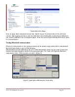
Page 48: ... Notes The Digi Connectware s Digi Device Discovery can be used to determine what IP address was assigned by the local DHCP server if any Digi Device Discovery can also be used to open a web interface to the Ethernet module Simply double click on the IP address that is displayed in the Digi Device Discovery utility Username root Password dbps If a mapped COM port is the desired communication metho...

Page 49: ...ress The Digi utility Digi Device Discovery can be used to determine the IP address that is currently assigned to the Ethernet module Hit Start All Programs Digi Connect Digi Device Discovery When the utility opens it scans the LAN looking for Digi Ethernet modules It may take a minute after plugging in or powering the Ethernet module before the LAN negotiates the connection with the Digi module H...

Page 50: ...ist of available profiles and click on apply at the bottom of the page The TCP Sockets profile settings will then be displayed Be sure that the box next to Enable Raw TCP access using TCP Port is selected and note the port number By default the port number is 2101 If any settings were changed click on apply at the bottom of the Port Profile Settings section Next select the Basic Serial Settings se...

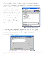
Page 51: ... been identified the unit is ready for communication Testing Ethernet Communication Ethernet communication to the pulse generator can be tested using a utility that is installed with National Instruments current VISA libraries After determine the IP address for the unit VISA Interactive Control can be used to send and receive command strings to and from the pulse generator Hit Start All Programs N...

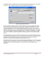
Page 52: ... support SCPI formatted command strings For these units command strings and responses are both terminated with text style line terminations a carriage return and linefeed pair These are ASCII characters number 13 and 10 respectively They are represented in this utility and in many other contexts as r n Figure 6 Session window for TCPIP resource In hexidecimal these are represented as 0x0D and 0x0A...

Page 53: ...uld return 0 000100000 or a simple ok r n to acknowledge a successful parameter change If a Read command does not follow each Write command the read output buffer in the pulse generator can overfill and become corrupt Many applications may need a communication mechanism no more sophisticated than what can be achieved with this simple utility At the very least this tool can be used to verify that t...

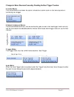
Page 54: ...ssed in the secondary channel menus To access this menu press the button for the channel of interest twice Continue to press then the Page button until the menu page with Ch Gate and TrigSrc appears Use the Next button to place the cursor on the TrigSrc line and use the up down arrows to change to the desired trigger source 9530 SCPI Dual Trigger Command Summary Keyword Command Sub Command Paramet...

Page 55: ...e which trigger source to use for that channel Ch HGFE DCBA Mux 0000 0001 Enable Disable Channel Ch Gate Dual Trig Trig Src Trig Ch HGFE DCBA Mux 0000 0001 Enable Disable Channel Ch Gate Dual Trig Trig Src Gate Press the Page Button Trigger Menu The Trigger menu now has a third mode selection Dual Trigger Mode Disabled Change Trigger Mode Mode Triggered Level 2 50 Volts Edge Rising Falling Edge Mo...

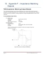
Page 56: ...le is the same as theAT20 modules including output while using theAdjustable Mode Function of the channels TTL ADJUSTABLE OUTPUTS TTL CMOS Mode Output Level 4 0 Volts typical into 50 Ω Rise Time 3 ns Slew Rate 0 5 V ns Jitter Channel to Channel 50 ps RMS Adjustable Mode Output Resolution 10 mV Current 200 mA typical 400 mA max short pulses Slew Rate 0 1 V ns Note The TZ50 module has significant ov...

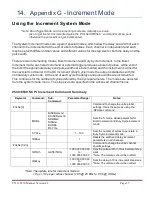
Page 57: ...normal duty cycle mode At the end of each cycle the delays and pulse widths are incremented This continues for the number of cycles defined by the Cycle parameters The modes are selected from the system mode menu The step sizes are specified in the advanced channel menus 9530 8530 SCPI Increment Command Summary Keyword Command Sub Command Parameter Range Notes PULSe 0 Command to change the units g...

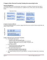
Page 58: ...riod Channel Advanced Menu The Channel Advanced menu now has a page where the user can set the Incrementing Width and Delay for each channel Ch HGFE DCBA Mux 0000 0001 Enable Disable Channel IncW Set the Incrementing Width IncD Set the Incrementing Delay Press the Page Button Using the Duty Cycle Increment Function In the System Mode menu o Set the mode to DCIncrement mode o Set the number of on a...

Page 59: ...ed number of pulses o Press the Page button and set the T0 period In the Channel menu o Set the desired pulse width and delay o Set the desired Channel Mode In the Channel Advanced menu o Set the desired width increment step size o Set the desired delay increment step size Via a serial interface send the PULSe0 IRESet 1 command to initialize the incrementing mode Once the Run Stop button is presse...

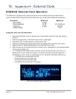
Page 60: ...ource menu is displayed Select the source to External Osc or External w PLL Adjust the threshold level appropriate for the amplitude of the external clock source Adjust the rate to match the frequency of the external clock source When the source is set to External Osc a lower case e will appear in the bracketed area of the screen Figure 10 A will appear if the system does not lock onto the externa...

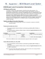
Page 61: ... even basic pulsing may begin Digital Control Board Connection Information Note The Power Input and Power Switch Connector are required connections for the 8530 module to function Power Input Connector J2 DC In The recommended connector is Molex 4 pin female C grid Molex 50 57 9404 or equivalent The recommended contacts are Molex female terminals with gold contacts Molex 16 02 0087 or equivalent P...

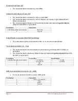
Page 62: ... on connector Clock Out 2 Ground Output Board Connection Mini PCB Card Edge This card edge must be connected to either J1 or J2 on the Output Board Fan Output Connector J1 Fan The recommended connector is Molex 4 pin female C grid Molex 50 57 9404 or equivalent The recommended contacts are Molex female terminals with gold contacts Molex 16 02 0087 or equivalent Pin Number Connection Specification ...

Page 63: ...6 5 Ground 6 DSR Connected to pin 4 7 RTS Connected to pin 8 8 CTS Connected to pin 7 9 N C Ethernet Communications Connector J7 Ethernet Module The recommended connector is a male RJ 45 Jack The pin out should be 568B or AT T 258A Pin Number Connection Wire Color 1 Tx Transmit Data Orange White 2 Tx Transmit Data Orange 3 Rx Receive Data Green White 4 N C Blue 5 N C Blue White 6 Rx Receive Data G...

Page 64: ...annel B Output C J4B Channel C Output D J5B Channel D Output E will only be present on 8 channel models J2A Channel E Output F will only be present on 8 channel models J3A Channel F Output G will only be present on 8 channel models J2B Channel G Output H will only be present on 8 channel models J3B Channel H Output Mounting Information There are 5 X 6 23 screw holes that should be used to mount th...

Page 65: ...9530 8530 Manual Version 4 5 Page 65 4 Channel Model when Digital Board is connected to J1 on the Output Board Figure 11 Connection Information for the 8534 ...

Page 66: ...Page 66 9530 8530 Manual Version 4 5 4 Channel Model when Digital Board is connected to J2 on the Output Board Figure 12 Connection Information for the 8534 ...

Page 67: ...9530 8530 Manual Version 4 5 Page 67 8 Channel Model when Digital Board is connected to J1 on the Output Board Figure 13 Connection Information for the 8538 ...

Page 68: ...Page 68 9530 8530 Manual Version 4 5 8 Channel Model when Digital Board is connected to J1 on the Output Board Figure 14 Connection Information for the 8538 ...

Page 69: ...9530 8530 Manual Version 4 5 Page 69 8530 Board Level Connector Locations Figure 15 Connector Information for the 8534 8538 ...

Page 70: ...Page 70 9530 8530 Manual Version 4 5 Figure 16 Mounting Information for the 8538 4 Channel Expansion Board ...

Reviews: