


QUANTECH
123
SECTION 6 - OPERATION
FORM QWC4-NM1 (221)
ISSUE DATE: 02/28/2021
6
LD16468
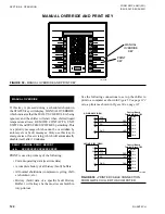
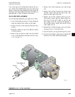
9-PIN RS-232 (DB9)
Control Board
Terminal Block TB1
NC
CTS
RD
GND
DSR
GND
TXD
25-PIN RS-232 (DB25)
4
8
2
5
11
20
5
3
7
RS-232
RS-232
NC
CTS
RD
GND
DSR
GND
TXD
TB1-1
TB1-2
TB1-3
TB1-4
TB1-5
TB1-6
TB1-1
TB1-2
TB1-3
TB1-4
TB1-5
TB1-6
Control Board
Terminal Block TB1
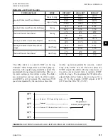
FIGURE 60 -
PRINTER CABLE CONNECTION
FROM QWC4 CHILLER TO A SERIAL PRINTER
ACCEPTABLE PRINTERS
The following printer can be used. Printers must be
equipped with an RS-232 serial interface.
Okidata OKIPOS 441 Printer
• Dimensions:
6.9 in. wide x 9.64 in. deep x 5.98 in. high
• Paper: 3.0 in. wide
• Type: Dot Matrix Impact
• Purchase: 800-OKIDATA
Spare printer Ribbon Okidata 52119001 Black
The control center provides the required formatting
control codes for the printers above when the printer
is selected on the PRINTER screen in the instructions
below. These codes are transmitted through the serial
interface to the printer to provide a proper print format.
Different printers require different formatting control
codes. Other printers might provide proper operation
when connected to the control center. However, the
print format may not be correct or as required.
Proceed with caution, and use the following guidelines
if an unlisted printer is selected:
1. All printers must be capable of RS-232 serial
communications.
2.
The primary differences between printers involve
the formatting control codes required by the print-
er, which are sent from the control center to the
printer. For example, Weigh -Tronix printers re-
quire a control code to select 40-column width.
This same code is interpreted by the Okidata
printer as an instruction to print wide characters.
In some instances, a printer will ignore a code it
cannot interpret.
3. The control center requires a busy signal from
the printer when the printer receive buffer is full,
which causes the control center to momentarily
terminate the data transmission until the printer
can accept more data. The busy signal polarity
must be asserted low when busy.
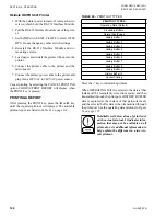
PRINTER CONNECTIONS
Connect the printers to the control center microboard
as follows. Only one printer can be connected at a time.
TABLE 39 -
OKIDATA OKIPOS 441
MICROBOARD PRINTER
FUNCTION
TB1-3
PIN 3
TX (Data to Printer)
TB1-2
PIN 20
DSR (Busy Signal
from Printer)
TB1-5
PIN 7
Ground
Cabinet
Shield
Required Hardware:
Cable
• #18 AWG stranded 50 ft maximum length.
Connectors
Microboard
• None. Strip 1/4 in. insulation from wire and insert
into screw terminal block.
Printers
• Okidata: 25 pin plug DB-25P or equivalent; Shell
DB-C2-J9 or equivalent.
PRINTER SETUP
The selected printer must be configured as follows. Re-
fer to the manual provided by the printer manufacturer.
Summary of Contents for QWC4
Page 14: ...QUANTECH 14 FORM QWC4 NM1 221 ISSUE DATE 02 28 2021 THIS PAGE IS INTENTIONALLY LEFT BLANK...
Page 64: ...QUANTECH 64 FORM QWC4 NM1 221 ISSUE DATE 02 28 2021 THIS PAGE IS INTENTIONALLY LEFT BLANK...
Page 82: ...QUANTECH 82 FORM QWC4 NM1 221 ISSUE DATE 02 28 2021 THIS PAGE IS INTENTIONALLY LEFT BLANK...
Page 130: ...QUANTECH 130 FORM QWC4 NM1 221 ISSUE DATE 02 28 2021 THIS PAGE IS INTENTIONALLY LEFT BLANK...
Page 146: ...QUANTECH 146 FORM QWC4 NM1 221 ISSUE DATE 02 28 2021 THIS PAGE IS INTENTIONALLY LEFT BLANK...
Page 152: ...QUANTECH 152 FORM QWC4 NM1 221 ISSUE DATE 02 28 2021 THIS PAGE IS INTENTIONALLY LEFT BLANK...
Page 155: ...QUANTECH 155 NOTES...