Channel type
Write channel numbers
Description
Units
Analog
none
-
PWM
0
−
1
PWM outputs
% duty cycle from 0-1
Digital
0
−
7
Reconfigurable digital I/O
8
LED
9
ESC enable
Other
11000
Left motor
Throttle from 0-1
11001
Right motor
Throttle from 0-1
11002
Front motor
Throttle from 0-1
11003
Back motor
Throttle from 0-1
Table 6.3: QBall 2 output channels
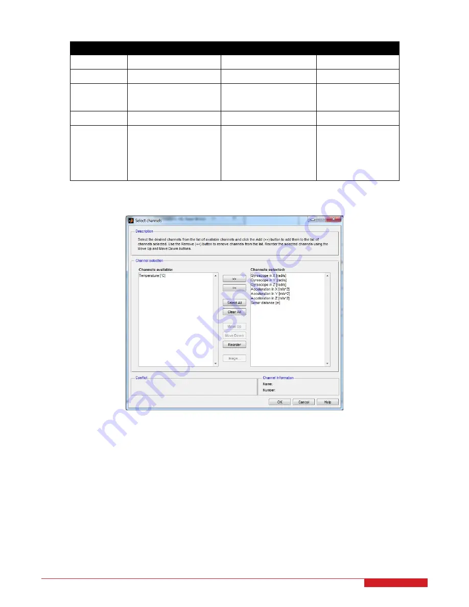
Figure 6.4: Channel selection dialog for the HIL Read Write block
For the QBall 2, the Other output channels
11000
−
11003
are used to command the front, back, left, and right
motors, respectively. The range of the motor output values is
0
to
1
(minimum throttle to maximum throttle), which
corresponds to a 1ms to
2
ms
PWM pulse, respectively. A command of
0
corresponds to zero throttle, which will
cause the motors to stop.
The
3
-axis gyroscope and accelerometer measurements are used to measure the QBall 2 dynamics and orientation
(roll, pitch and yaw). These IMU inputs are crucial for controlling the flight of the QBall 2. The QBall 2 DAQ utilizes
a STMicroelectronics
3
-axis gyroscope [6] and a Freescale
3
-axis accelerometer [7]. The QBall 2 sonar sensor is
the Maxbotix XL-Maxsonar EZ3, which measures distances between 20cm and 765cm with 1cm resolution. Objects
between 0-20cm are ranged as 20cm. The sonar sensor is positioned at the bottom of the QBall 2 and is used to
measure the QBall 2 height for closed-loop height control.
QBALL 2 - User Manual
20


