background image

Preface 

12 

QutePC-4100 Series User’s Manual 

Line conditioners keep a system’s AC power source voltage at a fairly constant 

level and, therefore, can handle brownouts. Because of this added protection, 

line conditioners cost more than surge protectors. However, line conditioners 

cannot protect against a complete loss of power. 


Uninterruptible Power Supply 

Uninterruptible power supply (UPS) systems offer the most complete protection 

against variations on power because they use battery power to keep the server 

running when AC power is lost. The battery is charged by the AC power while it 

is available, so when AC power is lost, the battery can provide power to the 

system for a limited amount of time, depending on the UPS system. 

UPS systems range in price from a few hundred dollars to several thousand 

dollars, with the more expensive unit s allowing you to run larger systems for a 

longer period of time when AC power is lost. UPS systems that provide only 5 

minutes of battery power let you conduct an orderly shutdown of the system, 

but are not intended to provide continued operation. Surge protectors should be 

used with all UPS systems, and the UPS system should be Underwriters 

Laboratories (UL) safety approved.

Summary of Contents for QutePC-4100 Series

Page 1: ...I QutePC 4100 Series User s Manual QutePC 4100 Series 0 6 Liter Box PC with Intel 3rd generation Core i3 3227U Processor User s Guide...

Page 2: ...patent rights of Quanmax nor the rights of others Quanmax is a registered trademark of Quanmax All trademarks registered trademarks and trade names used in this user s guide are the property of their...

Page 3: ...packing 8 Regulatory Compliance Statements 8 Warranty Policy 9 Maintaining Your Computer 10 Chapter 1 Introduction 13 Overview 13 Product Specifications 14 System tour 15 Mechanical Dimensions 18 Chap...

Page 4: ...ock 23 Table 1 QutePC 4100 series product specifications 14 Table 2 BIOS Main Menu 25 Table 3 Advanced Menu 26 Table 4 Advanced Menu Display Configuration 27 Table 5 Advanced Menu Power Management Con...

Page 5: ...Use extreme caution when installing or removing components Refer to the installation instructions in this user s guide for precautions and procedures If you have any questions please contact Quanmax...

Page 6: ...ts connector or on its strain relief loop not on the cable itself Some cables have a connector with locking tabs If you are disconnecting this type of cable press in on the locking tabs before disconn...

Page 7: ...re Don t touch the components or contacts on a board Hold a board by its edges or by its metal mounting bracket Do not handle or store system boards near strong electrostatic electromagnetic magnetic...

Page 8: ...or damage If there is damage notify Quanmax customer service immediately Refer to Warranty Policy for the return procedure Regulatory Compliance Statements This section provides the FCC compliance sta...

Page 9: ...mited Warranty Quanmax Inc s detailed Limited Warranty policy can be found under Support at www quanmax com Please consult your distributor for warranty verification The limited warranty is void if th...

Page 10: ...not in compliance with this Limited Warranty Return Policy will not be accepted by Quanmax Limitation of Liability In no event shall Quanmax be liable for any defect in hardware software loss or inad...

Page 11: ...tude low pressure reduces the efficiency of the cooling fans to cool the system This can cause electrical problems related to arcing and corona effects This condition can also cause sealed components...

Page 12: ...r running when AC power is lost The battery is charged by the AC power while it is available so when AC power is lost the battery can provide power to the system for a limited amount of time depending...

Page 13: ...erformance System is supported with Intel HM76 Express chipset and DDR3 SO DIMM up to 8GB Featured are 1x 2 5 SATA HDD 2x GbE 4x USB3 0 2x USB2 0 HDMI 2xDP Checklist QutePC 4100 Series Power Adapter P...

Page 14: ...DIF Rear I O panel 1x DC JACK 2x RJ 45 GbE ports 2x DP 1x HDMI 1x 3G Antenna Optional 1x Clear CMOS Storage QutePC 4100 1x 500GB 2 5 SATA HDD QutePC 4101 1x 320GB 2 5 SATA HDD QutePC 4102 1x 32GB 2 5...

Page 15: ...e devices cameras and hard disk drives USB allows many devices to run simultaneously on a single computer with some peripheral acting as additional plug in sites or hubs WiFi LED The WiFi LED will lig...

Page 16: ...r supplied through this jack supplies power to the PC To prevent damage to the PC always use the supplied power adapter Kensington Lock Slot The slot is used for attaching a lock and cable apparatus L...

Page 17: ...Chapter 1 17 QutePC 4100 Series User s Manual Wireless 1x reserved holes for wireless antenna connections Clear CMOS 1x reset button for clear CMOS...

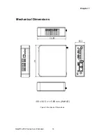
Page 18: ...Chapter 1 18 QutePC 4100 Series User s Manual Mechanical Dimensions 130 x 38 5 x 115 86 mm WxHxD Figure 3 Mechanical Dimensions...

Page 19: ...hapter 2 19 QutePC 4100 Series User s Manual DP HDMI Chapter 2 Getting Started Setting up your PC Connecting the monitor Connect the DP HDMI cable from your display to the DP HDMI port Figure 4 DP HDM...

Page 20: ...s does not come with a keyboard and mouse but you can use any USB keyboard or mouse with your computer Figure 5 Connecting USB mouse keyboard NOTE Using a third party USB mouse or keyboard may require...

Page 21: ...nel and the other end to a hub or switch Figure 6 RJ45 connector Turning on the system 1 Connect the power adapter cable to the DC jack DC IN of the QutePC 4100 series 2 Connect the power cable to the...

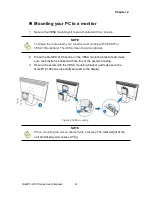
Page 22: ...d The VESA mounting kit is optional 2 Place the QutePC 4100 series on the VESA mounting bracket and make sure the bracket is hooked with the fins of the system housing 3 Secure the screw with the VESA...

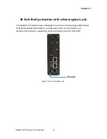
Page 23: ...th a Kensington Lock The QutePC 4100 series has a Kensington lock slot for the Kensington MicroSaver With the Kensington MicroSaver a sturdy steel cable you can attach your QutePC 4100 series to a sta...

Page 24: ...please contact Quanmax AMI s ROM BIOS provides a built in Setup program which allows the user to modify the basic system configuration and hardware parameters The modified data will be stored in a ba...

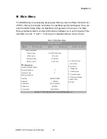
Page 25: ...Table 2 BIOS Main Menu BIOS SETUP UTILITY M a i n A d v a n c e d B o o t S e c u r i t y S a v e E x i t Product Information Select Screen Select Item Enter Select Change Opt F1 General Help F2 Previ...

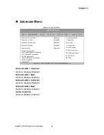
Page 26: ...LAN 1 Boot Disabled Onboard LAN 2 Controller Enabled Onboard LAN 2 Boot Disabled Audio Controller Enabled Display Configuration Power Management Configuration CPU Advanced Configuration SATA Configura...

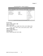
Page 27: ...F2 Previous Values F3 Optimized Defaults F4 Save Exit ESC Exit Aperture Size 256 MB DVMT Pre Allocated 64 MB DVMT Total Gfx Mem 256 MB IGFX Boot Type VBIOS Default Version 2 15 1236 Copyright C 2012 A...

Page 28: ...3 Suspend to RAM Restore AC Power Loss Power Off Resume By PCIE Device Disabled Resume By RTC Alarm Disabled EUP Power Saving Mode Disabled Watchdog Timer Configuration Version 2 15 1236 Copyright C 2...

Page 29: ...2 Previous Values F3 Optimized Defaults F4 Save Exit ESC Exit EIST Enabled Active Processor Cores ALL Limit CPUID Maximum Disabled Execute Disable Bit Enabled Intel Virtualization Technology Disabled...

Page 30: ...SATA Device Type Unknown Enabled Hard Disk Driver Version 2 15 1236 Copyright C 2012 American Megatrends Inc SATA Controller s Options Disabled Enabled SATA Mode Selection Options IDE AHCI SATA Contro...

Page 31: ...y USB Support Enabled USB3 0 Support Enabled xHCI Hand off Enabled EHCI Hand off Disabled USB Mass Storage Driver Support Enabled xHCI Pre Boot Driver Enabled xHCI Mode Smart Auto Version 2 15 1236 Co...

Page 32: ...zed Defaults F4 Save Exit ESC Exit CPU Warning Temperature Disabled CPU FAN Configuration CPU Temperature 55 C Memory Temperature 36 C System Temperature 42 C CPU FAN Speed N A VCORE 0 736V VIN 19 447...

Page 33: ...nter Select Change Opt F1 General Help F2 Previous Values F3 Optimized Defaults F4 Save Exit ESC Exit Full Screen LOGO Display Disabled Setup Prompt Timeout 1 Bootup NumLock State On UEFI Boot Disable...

Page 34: ...n the following range Minimum Length 3 Maximum length 20 Administrator Password User Password Select Screen Select Item Enter Select Change Opt F1 General Help F2 Previous Values F3 Optimized Defaults...

Page 35: ...e BIOS asks for a confirmation before exiting Discard Changes Discards changes done so far to any of the setup values This option allows you to discard the selections you made and restore the previous...

Page 36: ...ng system and the necessary drivers to operate it After you have finished assembling your system and connected the appropriate power source power it up using the power supply and install the desired o...

Reviews: